QR Clock Is Unreadable By Humans And Computers Alike

The clock is a perfect technology. For just a few dollars, you can buy a digital wristwatch and chronometer able to keep extremely accurate time for years without winding a spring or replacing a battery. Anything ‘improvement’ on the design of a clock only makes it harder to read, a feature exploited by the very 1337 binary clocks we see from time to time. [Ch00f] decided it was time to give way to the march of progress and build a completely unreadable clock. He came up with a QR code clock that is unreadable by humans and cellphones alike.

The hardware is built around nine 8×8 LED matrix panels resulting in a 24 x 24 pixel display, perfect for displaying a 21 pixel square QR code. The LED drivers are a standard multiplexed affair, but this project really shines in the firmware department.

The microcontroller [Ch00f] used – an ATMega328 – is far too small to store the 1440 QR codes for every minute of the day. No, this project would have to dynamically generate QR codes on the fly, not exactly an easy problem.

After looking over the official QR code standard, [Ch00f] wrote a rather large program that turns alphanumeric sequences into QR code. This runs on the microcontroller every minute, generating a new QR code for every minute of the day.

It’s nigh impossible for a human to read a QR code, but [Ch00f] figured he could make his project even less useful. By multiplexing the LEDs at a very low duty cycle [Ch00f] made it impossible for a camera to capture the entire QR code, even though the pattern of pixels is still visible to the human eye. A fabulously useless build that really steps up the game for unreadable clocks.

Video after the break.

Continue reading “QR Clock Is Unreadable By Humans And Computers Alike”

Nebulophone Microcontroller Synthesizer Project Sounds Great

Judging from the video (found after the break) the Nebulophone is one of the best sounding DIY synthesizers we’ve seen. Especially when you consider the simplicity of the hardware design. It uses an AVR chip and an OpAmp. The rest of the parts are just a few handfuls of inexpensive components.

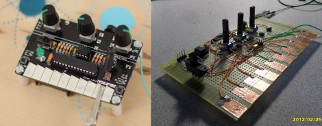
The device was developed by Bleep Labs, and they sell the synthesizer kit seen on the left. But since it’s an open source project you can follow their design to fabricate your own, which is what [BlinkyBlinky] did with his offering seen to the right.

An ATmega328 drives the device, which is the chip often used in the Arduino Duemilanove. The keyboard is a set of traces hooked to the microcontroller. These are tinned pads on the kit PCB, but the DIY version simply uses some adhesive copper foil with a jumper wire soldered to it. The keys are played with a probe that makes the electrical connection, a common practice on these stylophone type designs. Chances are you have everything on hand to make this happen so keep it in mind for that next cold winter weekend that’s making everyone a bit stir crazy.

Continue reading “Nebulophone Microcontroller Synthesizer Project Sounds Great”

Build A POV Death Star, You Will

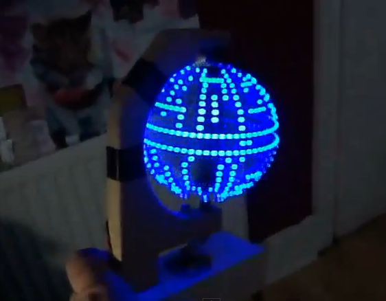
Building a Persistence of Vision globe is pretty awesome, but overlaying a Death Star pattern on the display takes it to the next level of geekery. Like us, [Jason] has wanted to build one of these for a long time. His success pushes us one step closer to taking the plunge and we hope it will inspire you to give it a shot too.

As he mentions in the beginning of his write up, the mechanical bits of these displays are really where the problems lie. Specifically, you need to find a way to transfer power to the spinning display. In this case use went with some DC motor brushes. These are replacement parts through which he drilled a hole to accept the metal axles on top and bottom. We hadn’t seen this technique before, but since motor brush replacements are easy to find and only cost a few bucks we’d say it’s a great idea.

The 24 blue LEDs that make up the display are all on one side of the PCB. They’re driven by an ATmega328 running the Arduino bootloader. [Jason] uses an FTDI adapter to program the chip. Don’t miss the video embedded after the break.

Continue reading “Build A POV Death Star, You Will”

Toothbrush Timer

This toothbrush holder will make sure you’re brushing your pearly whites for an appropriate length of time. The three cups serves as tootbrush storage, and detect when one has been removed. Once you start brushing your teeth the lights on the front and bell in the back count down the process automatically.

The counting sequence starts when a weight sensor in the base detects a change caused by picking up a toothbrush. The ATmega328 — which is programmed with Arduino-style code — then turns on all of the incandescent lamps mounted on the front portion of the base. Each of these are switched with a 2N3904 transistor in order to sink enough current for the bulb. As a two-minute timer decrements, the bulbs are extinguished one by one. But there is also an auditory feedback mechanism. On the back of the base is a small bell. A hammer on a servo strikes the bell every 30 seconds to let you know how you’re doing. The entire thing is driven by an internal Li-ion battery which lasts about three weeks between charges. Don’t miss the demo video found after the break.

Continue reading “Toothbrush Timer”

Adding A Heart Rate Monitor To Your Exercise Equipment

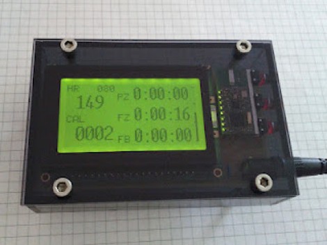
This is the readout which [Remick] added to his stationary bicycle. It displays heart rate, calories burned, and a few other items to help motivate his workout routine.

Back when he was ordering a TI Chronos watch he also picked up a heart rate chest strap and receiver. The receiver can be read using a UART, making it easy to interface with the ATmega328 which drives the system. The screen is a graphic LCD, which gave him a lot of control on how to organize the displayed data. Three buttons on the side operate the menu system into which a user can enter sex, age, and weight information. This is used to calculate the calories burned and the percentage of maximum heart rate. The three readouts to the right are for time spent in each workout zone (fat burning, fitness, or performance). The final product looks great because of the PCB he etched and the case he housed it in.

Taking A Moon Light From Grayscale To Full Color

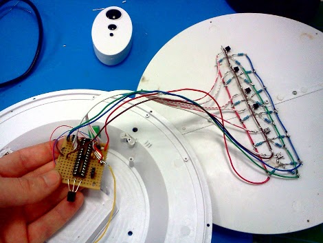
[Terry Miller] picked up a moon light on the cheap. All it does is light up some white LEDs to simulate moon phases after sensing nightfall via an LDR. He figured he could do better and set out to replace the electronics with a more colorful offering.

He chose to use an ATmega328 because he already had it on hand. The chip drives a series of RGB LEDs in a multiplex arrangement. To protect the I/O pins (and drive the LEDs at their target current) he is using a set of high and low side MOSFETs. Rather than rely on the light sensor to switch on the lamp he decided to add an IR receiver. In the video after the break you can see that this lets him cycle through colors and effects, in addition to switching the lamp on and off with a remote control.

With the enclosure put back together he is still able to reprogram the chip thanks to a serial header included in the design. The device is battery operated and the life estimates are included in his write-up.

Continue reading “Taking A Moon Light From Grayscale To Full Color”

Red Bull Creation Hardware (Bullduino) Arrives

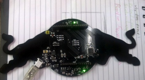
The Bullduino’s are starting to arrive. When [Arclight] received his in the mail the first thing he did was to share the hardware details. Of course this is the hardware that participants in the Red Bull Creation contest will be receiving ahead of this year’s contest.

The board is an ATmega328 Arduino clone. Instead of an FTDI chip for USB this one is sporting an ATmega8u2. That’s not too much of a surprise as it should translate to a cost savings. [Arclight] reports that the stock firmware flashes a message in Morse code. It seems the Harford HackerSpace got their Bullduino several days ago and already decoded the message. It reads:

“Wouldn’t lou prefer a good game of chess?”

The guys that did the decoding speculate that this could be a type as ‘l’ and ‘y’ are inversions of each other in Morse code; or it could be some kind of clue. At any rate, if you want to do some disassembly and see if there’s anything lurking in the firmware, [Arclight] posted FLASH and EEPROM dumps from both ATmega chips along with his article.