On the face of it, playing a vinyl record is a simple process. You simply mount it on a turntable rotating at the right speed, and insert a needle into the groove. A learning exercise for youngsters used to be a passable attempt at a record player on the kitchen table with a pencil, a large cork, a sharpened matchstick, and a piece of paper. It sounded awful, but it demonstrated well how the audio was recorded.
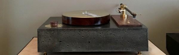
If you have ever looked into the operation of a more conventional turntable though you’ll know that a little more care and attention is needed. There are many factors which affect the quality of the sound, and you quickly become obsessive about tracking, and sources of the tiniest vibration. Someone who has followed this path is [Mjhara], who has made a very high quality turntable. There is an unusual choice in this project: the tonearm is part of the build rather than fitting a commercial item like most turntable projects.
 The platter is machined from a piece of rosewood, weighted and balanced with lead shot, and laminated between two sheets of brass. It sits on a bearing aided by a ring of opposing magnets, and is belt driven by a two-phase induction motor. The base of the turntable is cast as a single piece of concrete, the idea being that the extra weight will aid the damping of vibrations. The tonearm is machined from a piece of wood, and its pivot from brass. The tonearm bearing is a ballpoint pen, a surprising yet inspired choice .
Sometimes audiophiles take their quest for better sound to extremes, and justification for their expenditure can be very subjective. But [Mjhara] assures us that this turntable has an exceptionally good sound, and it is certainly a thing of beauty. Full details are in the Imgur gallery embedded below the break.
Continue reading “A Beautiful Turntable With A Heart Of Concrete” →