If there is one tool every hardware hacker needs, it’s a good soldering setup. Soldering irons, heat guns, reflow ovens and the like make up the tools of the trade for building electronic circuits. Spend enough time working with a tool, and you’ll find a way to improve it. It’s no surprise that hackers, makers, and engineers have been hacking their soldering tools for decades. This week’s Hacklet features some of the best soldering tool projects on Hackaday.io!
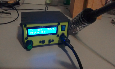 We start with [Kuro] a Hakko 907 based Soldering Station. Hakko 907 and 936 soldering station clones from the Far East are available all over the internet. While the heaters work, none of them have very good temperature controllers. [Kuro] turned a problem into a project by building his own soldering station. These irons are rated for 24 V. 24 volt power supplies are not very common, but it’s easy to find old 19 volt supplies from discarded laptops. [Kuro] found that the lower voltage works just fine. An Arduino nano controls the show, with user output displayed on a 2 line LCD. The finished controller works better than the original, and probably would give a real Hakko model a run for its money.
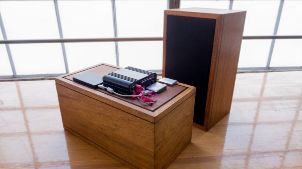
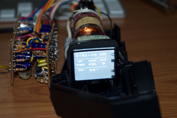
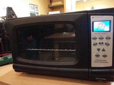 Next up is [Sukasa] with Reflow Oven. When MakerSpace Nanaimo needed a reflow oven, [Sukasa] jumped in with this design. The idea was to create an oven that looked unmodified – just think of it as the toaster oven of the future, or the reflow oven of today. A Netduino plus 2 is the main controller. User information is displayed on a color TFT LCD. This oven is even internet connected, with an internally hosted web page and JSON data feed. The Netduino controls two beefy Solid State Relays (SSRs). The SSRs handle the dirty work of switching the oven’s heating elements. Two fans keep air moving to avoid hot spots. Precision temperature sensing is achieved through a pair of Adafruit MAX31855 breakout boards reading thermocouples.
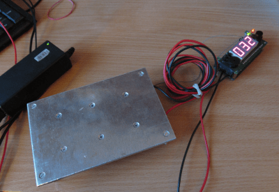 Next we have [Jaromir Sukuba] with Soldering preheat plate. When soldering surface mount components, like QFN or BGA parts, it helps to pre-heat the whole board. There are commercial products to do this using hot air and other techniques, but it really comes down to making a hotplate. [Jaromir] figured he could do a pretty good job at this, so he built his own with a 3mm aluminum plate. Heat comes from 6 resistors in TO-220 cases. A Microchip PIC18 monitors a thermocouple and keeps things from getting too hot. For power, [Jaromir] had the same idea as [Kuro] did, and used a 19V power brick from an old laptop.
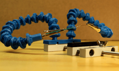 Finally we have [Alex Rich] with Locking ball and socket gooseneck system. [Alex] came up with the Stickvise, so it’s fitting that he comes up with an awesome upgrade for it. We’ve all fought with “helping hands” while soldering. You never get them at quite the right angle. This system fixes that with a simple ball and gooseneck setup. [Alex] saw a similar design and printed it out. While it worked, the pieces popped apart too easily. [Alex] redesigned the system, adding a threaded locking ring. These new goosenecks stay put, holding your work exactly where you want it.
If you want to see more soldering tool projects, check out our brand new soldering tools list! If I missed your project, don’t be shy! Just drop me a message on Hackaday.io. That’s it for this week’s Hacklet. As always, see you next week. Same hack time, same hack channel, bringing you the best of Hackaday.io!