The Practical Approach To Keeping Your Laser In Focus

You could be forgiven for thinking that laser cutters and engravers are purely two dimensional affairs. After all, when compared to something like your average desktop 3D printer, most don’t have much in the way of a Z axis: the head moves around at a fixed height over the workpiece. It’s not as if they need a leadscrew to push the photons down to the surface.

But it’s actually a bit more complicated than that. As [Martin Raynsford] explains in a recent post on his blog, getting peak performance out of your laser cutter requires the same sort of careful adjustment of the Z axis that you’d expect with a 3D printer. Unfortunately, the development of automated methods for adjusting this critical variable on lasers hasn’t benefited from the same kind of attention that’s been given to the problem on their three dimensional counterparts.
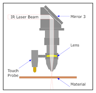
Ultimately, it’s a matter of focus. The laser is at its most powerful when its energy is concentrated into the smallest dot possible. That means there’s a “sweet spot” in front of the lens where cutting and engraving will be the most efficient; anything closer or farther away than that won’t be as effective. As an example, [Martin] says that distance is exactly 50.3 mm on his machine.

The problem comes when you start cutting materials of different thicknesses. Just a few extra millimeters between the laser and your target material can have a big difference on how well it cuts or engraves. So the trick is maintaining that perfect distance every time you fire up the laser. But how?

One way to automate this process is a touch probe, which works much the same as it does on a 3D printer. The probe is used to find where the top of the material is, and the ideal distance can be calculated from that point. But in his experience, [Martin] has found these systems leave something to be desired. Not only do they add unnecessary weight to the head of the laser, but the smoke residue that collects on the touch probe seems to invariably mar whatever surface you’re working on with its greasy taps.

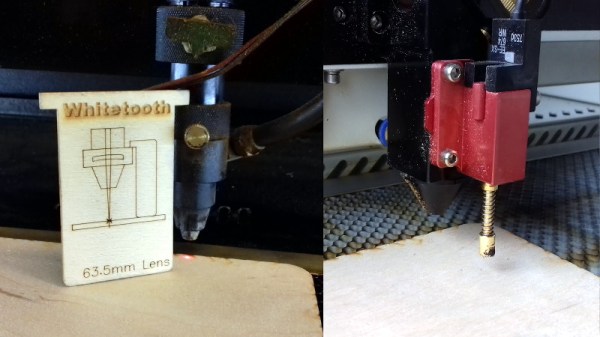
In his experience, [Martin] says the best solution is actually the simplest. Just cut yourself a little height tool that’s precisely as long as your laser’s focal length. Before each job, stick the tool in between the laser head and the target to make sure you’re at the optimal height.

On entry level lasers, adjusting the Z height is likely to involve turning some screws by hand. But you can always add a motorized Z table to speed things up a bit. Of course, you’ll still need to make sure your X and Y alignment is correct. Luckily, [Martin] has some tips for that as well.

Sonic 3D Printer Auto Bed Leveling Makes A Swoosh

3D Printering: the final frontier. These are the voyages of another 3D printer hack. Its mission: to explore strange new ways of leveling a print bed.

So far, we’ve had servo probes, Allen key probes, Z-sled probes, inductive and capacitive contactless switches, just to name a few. All of them allow a 3D printer to probe its print bed, calculate a correction plane or mesh, and compensate for its own inherent, time variant, inaccuracies.

Continue reading “Sonic 3D Printer Auto Bed Leveling Makes A Swoosh”

semi auto bed leveling

Semi-Automatic Bed Leveling Your 3D Printer

Two of the most important prerequisites for successful 3D printing is making sure the bed is level and correctly setting the Z=0 height. Getting both of these right almost guarantees great adhesion since the first print layer is not only at the right distance from the build platform but also at a consistent distance for the entire bottom surface of the part.

Manual bed leveling is tedious, requiring the user to move the print nozzle to different points around the build platform, adjust some screws and make sure the nozzle is a piece-of-paper’s thickness higher than the platform. If you want to get complicated, there is an automatic option that probes the build platform and makes height corrections in the software. The probes come in several flavors, two common methods being a deployed mechanical switch (usually mounted to a servo) or force sensors under the build platform that sense when the nozzle touches the build platform. This method also requires some fancy firmware finesse to get working correctly.

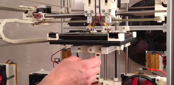
[Jonas] posted a video showing the semi-automatic bed leveling capability of his printer. The build platform is held a bit high by springs that surround each of the 3 screws that support the bed assembly. The nozzle is moved directly over one of the 3 screws and then moved down until it noticeably presses on the build platform, compressing the support spring. A thumb wheel is then tightened at that location, locking the bed in place. The same process is performed for the other 2 support points. The result is a perfectly level build surface. Check the video out after the break to see just how quick this procedure is!

We’ve seen a somewhat similar concept that uses a clever gimbal and lock system under the bed.

Continue reading “Semi-Automatic Bed Leveling Your 3D Printer”

Automated Bed Leveling For 3D Printers Is Now Solved

The latest and greatest feature for 3D printers – besides being closed source, having no meaningful technical specs, and being on track towards pulling in $10 Million on a Kickstarter – is automated bed leveling. This amazingly useful feature makes sure your prints have proper adhesion to the bed, reduce print errors, and put even inexpensive printers into the realm of extremely expensive professional machines. Automated bed leveling has been extremely hard to implement in the past, but now [Scottbee] has it figured out with a working prototype on his Makerbot Replicator 2X.

Earlier attempts at automated bed leveling used some sort of probe on the tool head to measure the build plate, calculate its flatness and orientation in space, and compensate for any tilt in software. [Scottbee]’s solution to the problem took a different tack: instead of trying to compensate for any odd orientation of the build surface in software, he’s simply making the bed level with a series of springs and cam locks.

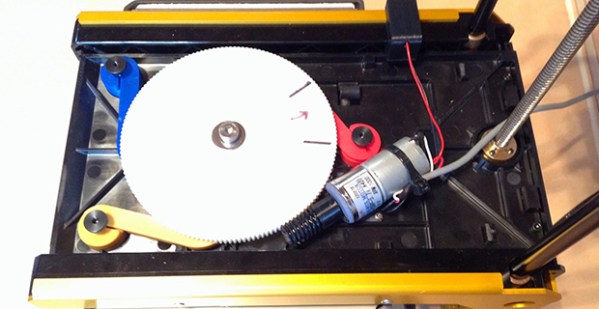
[Scottbee]’s device levitates the build plate on three springs, and replaces the jack screws with three “gimballing pins” and pin locks. With the pin locks disengaged, the bed plate is pressed down with the printer’s nozzle. By moving the extruder across the build plate and locking the pins in place one by one, [Scottbee]’s device defines the plane of the build plate along three points. This makes the build platform parallel to the extruder nozzle, and also has a nice benefit of setting the distance from the build platform to the nozzle precisely with incredible repeatability.

The mechanics of locking the three gimballing pins in place  only requires a single DC gear motor, driven by an extra fan output on the Makerbot’s electronics. It’s simple, and with a bit of rework, it looks like most of the device could also be 3D printed.

An awful lot of RepRaps and 3D printers out there already use three points to attach the build plate to a frame. With a little bit of effort, this same technique could be ported and made a bit more generic than the Makerbot-based build seen above. It’s amazingly simple, and we can’t wait to see this applied to a normal RepRap.

Thanks [Josh] for the tip.

Ask Hackaday: Auto Bed Leveling And High Temperature Force Sensitive Resistors

FSR

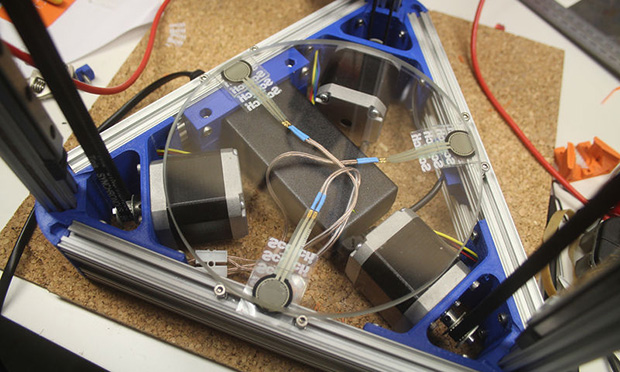
[Johann] over on the RepRap wiki has an ingenious solution for making sure a borosilicate glass bed is completely level before printing anything on his Kossel printer: take three force sensitive resistors, put them under the build platform, and wire them in parallel, and connect them to a thermistor input on an electronics board. The calibration is simply a bit of code in the Marlin firmware that touches the nozzle to the bed until the thermistor input maxes out. When it does, the firmware knows the print head has zeroed out and can calculate the precise position and tilt of the bed.

Great, huh? A solution to bed leveling that doesn’t require a Z-probe, uses minimal (and cheap) hardware, and can be retrofitted into just about any existing printer. There’s a problem, though: these force sensitive resistors are only good to 70° C, making the whole setup unusable for anything with a heated bed. Your challenge: figure out a way to use this trick with a heated bed.

The force sensitive resistors used – here’s a link provided by [Johann] – have a maximum operating temperature of 70° C, while the bed temperature when printing with ABS is around 130° C. The FSRs are sensitive to temperature, as well, making this a very interesting problem.

Anyone with any ideas is welcome to comment here, on the RepRap forums, the IRC, or anywhere else. One idea includes putting an FSR in the x carriage, but we’re thinking some sort of specialized heat sink underneath the bed and on top of the FSRs would be a better solution.

Video of the auto bed leveling trick in action below.

Continue reading “Ask Hackaday: Auto Bed Leveling And High Temperature Force Sensitive Resistors”