Breakout Board For $11 LCD Module With Small Pitch

breakout-for-strange-pitch-LCD-screen

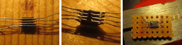
[Ibrahim] picked this little LCD module out because of its price point and resolution. In single units you can grab one of the 128×32 pixel displays for just $11. The only problem is that the pinout is too small to use with a breadboard. He whipped up a breakout board for it that throws in some extras.

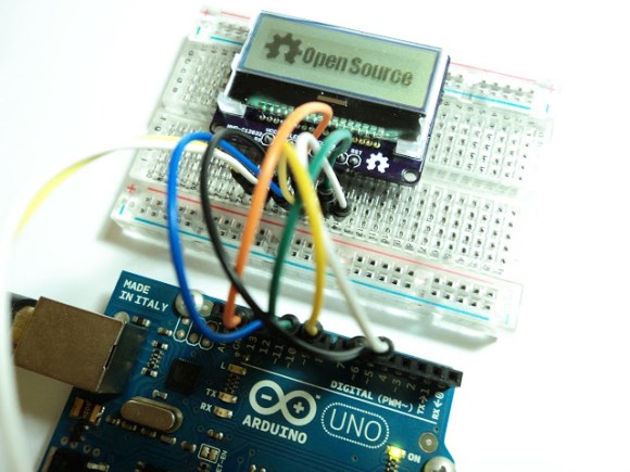
First off, we like it that the board doesn’t add much to the part’s outline. What it does add is a Low-DropOut voltage regulator and a level converter. The upper range of the LCD’s input voltage is 3.3V, and these added parts make it possible to drive the device using 5V hardware like the Arduino Uno pictured above. While he was adding in parts he included a MOSFET to switch the backlight. This way he can use PWM for dimming as well.

We usually hit eBay when looking for LCD screens. A search for the NHD-C12832 part number didn’t turn it up. We tried out FindChips for the first time (owned by Supply Frame who just bought Hackaday) and it works just as well as Octopart which we’re more familiar with since we’ve seen some hacking of that site before.

Solder Trick To Make Your Own Surface Mount Breakout Boards

surface-mount-breakout-trick

We think you’re really going to enjoy this trick for making surface mount breakout boards. It’s common to use magnet wire to connect individual pins of a surface mount part to breadboard friendly protoboard with pin headers. What’s new here (at least to us) is that [Raul] solders one wire to both pins directly across from one another.

The image at the left shows an eight pin part with four wires soldered in place. To get to this point he first taped the wires down to a work surface being careful to space them to match the pitch on the chip’s leads. He then tapes the chip in place and solders all of the legs to the wires. This seems to kill two birds with one stone as aligning one wire to one leg is tough. From there he flips the chip over and cuts the wire spanning under it. This leaves an easy job of soldering the trailing side of the wire to a hunk of protoboard.

It’s perfect for chips with a small number of pins. Of course you may still want an etched breakout board for something with a ton of leads.

Hand Soldering BGA Parts Should Be A Circus Act

Okay, we think it’s questionable when people say they have no problem soldering QFN packages, but BGA? Granted this chip has far fewer balls on it than many, but it’s still quite impressive that [Xevel] was able to solder this BGA breakout by hand.

The chip you see above is a TMP006 infrared temperature sensor from TI. [Xevel] picked up the part but didn’t want to break the bank when prototyping by buying a proper PCB to host it. There are only eight conductors on it, arranged in a grid with 0.5mm pitch. That didn’t seem to scare him off, as the video after the break shows him connecting each to a conductor on a hunk of stripboard.

[Xevel] mentions that this is a dead-bug style project. Usually you glue the part upside down when using that technique, but it needs line of sight to get an accurate temperature reading so he first cut a hole in the substrate. We’d bet he’s using wire-wrapping wire to make the connections. It’s a very fine solid core wire which is perfect for this kind of work.

Continue reading “Hand Soldering BGA Parts Should Be A Circus Act”

PIC 18F4550 Dev Board

[Natsfr] was looking for a single-sided PCB to host a PIC 18F4550. Not finding one he designed his own in Kicad and is sharing (translated) the spoils of his labor.

This chip has USB capabilities which is why we see it used in a ton of projects. Almost all of them (including this USB input device post) use a very large DIP package. [Natsfr] went a different route, designing for the TQFP package to keep the drilling ot a minimum. The layout includes a crystal and USB-mini port, but it also breaks out the I/O pins on the chip. The red box above shows the quick fix he used on the VCC line as the board trace was shorting on the USB jack housing.

He didn’t drill out the holes for most of the breakout pins on this prototype. There’s just one header populated for programming the PIC chip. But he does have some plans for the first board. He’s going to use [Texan’s] AVR programming firmware for PIC to turn it into a USB AVR ISP programmer.

Prototyping With Very, Very Small ICs

Gone are the days when all the cool chips are able to be thrown into a breadboard very easily. [starlino] was working with a circuit that uses an accelerometer, but unfortunately these chips come in hard to solder LGA-16 packages. [starlino] figured out a way to prototype with these packages that doesn’t require a custom breakout board or spending any time watching a reflow oven.

[starlino]’s LGA-16 adapter board began with a piece of perf board drilled out to form a space that perfectly fits his accelerometer. A piece of tape is placed over the pads of the chip and perf board, and the gap between the chip and board is filled in with a two-part plumbers putty.

Once the putty has cured, the leads on the acclerometer are connected to the pads on the board with a silver conductive pen. After putting a few header pins in the corners of the board, [starlino] soldered the pads to the pins and had a permanent breakout board for a very small accelerometer.

It’s not by any means a pretty build, but after [starlino] sealed the entire build in liquid electrical tape and installed it in a DIP socket, he had a completely functional accelerometer in an easy to prototype package. Not bad for a breakout board that can be built from stuff just lying around a workbench.

Giving An ATX Bench Supply The Case It Deserves

Your bench supply doesn’t need to look sad just because you’re using an ATX power supply instead of a commercial product. Follow [Ian Lee’s] example and you could have beautiful wooden enclosures for the tools in your own shop.

The woodworking skills used here aren’t all that advanced, but you need to have a knack for it so we suggest running some test pieces before you start the actual build. [Ian] ran a dado for the front and back panel in each piece of the wood sides. At each corner the inside of the the pieces were mitered at 45 degrees. To put it all together he laid the pieces end to end on a the work bench, then applied painters tape to the outside of the joints. This holds the joints together so that he can flip the collection over, apply glue, and then start hinging the sides into place. It’s almost like rolling up a box.

As with other ATX supply projects we’ve seen [Ian] designed this so that the PSU can be swapped out later if necessary. Instead of wiring his own cable harness he used an ATX breakout board. To get the interface layout he wanted he mounted the banana jacks separately and just ran jumper cables back to that board.

Resizable ARM Dev Board; Just Take Some Off The Top

[Bob Alexander’s] most recent project is a hack saw resizable ARM breakout board. He wanted to start using more ARM microcontrollers in his projects and went for a breadboard friendly design. It uses a 40-pin dip package, but if you need the horsepower but not the I/O you can literally cut it down to size. We might recommend grabbing some tin snips, which can cut through a PCB like butter, but to each his own.

The board is based around an STM32 chip. You’ll find a crystal oscillator for the system clock, and a clock crystal if you need it. On the other side of the chip he included a footprint for a voltage regulator. This setup provides a remarkable range of input voltages, accepting from 2 to 3.6 volts without the regulator, and up to 16 volts if the regulator is present. He designed a package footprint that can be easily bridged if there’s no SMD part there. Just make sure you insulate that pad if you are using one with a conductor on the bottom. He explains this in detail in his writeup.

You’ll need a programmer to work with the board. He uses an STM32 Discovery Board for this but there are quite a few other options out there too.