Glass PCB LED Clock

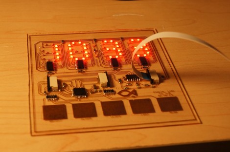
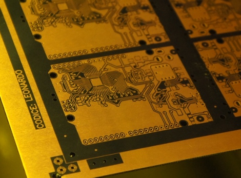
This clock looks fantastic because of the glass PCB used for the build. This banner image allows you to see all the traces and components, but when it is lifted off of the desk surface the LEDs which make up the 7-segment digits appear to be floating.

The concept isn’t new, but it’s a much larger format than we’ve seen before. When we first looked at [CNLohr’s] glass PCB fabrication he was using microscope slides. This uses a much larger pane of glass but it seems the fabrication still uses copper foil glued to the glass, then toner transfer etched like normal.

Here he’s testing out some 74LV164 chips as constant current drivers. One of the commenters on the Reddit thread is skeptical about using the chip in this way and so are we. But as the video after the break shows, it seems to work (at least for now). [CNLohr] also mentions that the AVR soldered on the display is burnt out which doesn’t help his case. Still, we love the look and can’t wait to see where he goes from here!

Continue reading “Glass PCB LED Clock”

Vapor Phase Reflow Soldering

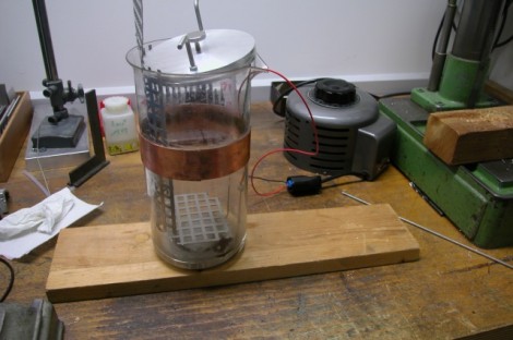
Ditch that old toaster oven and move to the next level of surface mount soldering with this vapor phase reflow method. [Ing.Büro R.Tschaggelar] put together this apparatus to use vapor phase reflow at his bench instead of sending out his smaller projects for assembly. It uses the heating element from an electric tea kettle to boil Galden HT 230 inside of a Pyrex beaker. There’s a copper heat break part way up the beaker to condense the chemical and keep it from escaping. When a populated board is lowered into the heated chamber, the solder paste reflows without the need to stress the components with unnecessary heat. Better than traditional reflow? At this level it’s hard to say, but we do find his method quite interesting.

[Thanks Chris]

Art Piece From Board Artwork

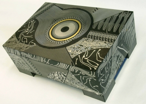
[Theo Kamecke] is an artist who produces striking pieces using printed circuit boards. We’ve seen PCBs used as faux stained-glass before, but [Theo’s] craftsmanship stands apart from everything we’ve seen. His webpage has at least one piece that sites the usage of vintage 1960’s circuit boards, but we wonder if he doesn’t design some of these to suit his work. Either way, we’d love to see him take on the finish work for that mechanized expanding round table we saw back in June. See more of his work on his photostream.

[Photo Credit]

[Thanks Mowcius]

Tools: Proxxon Drill Press TBM115/TBM220

tbm220ii

A decent drill press is a crucial tool for an electronics lab. We use our drill press to make holes in our own circuit boards, and tap or break traces on existing circuit boards. We’ve used a lot of tools to drill circuit boards — power drills, power drills in “drill press stands”, and high-speed rotary tools — but when we started doing projects on a schedule, it was time for something more reliable.

We first spotted the Proxxon TBM115/TBM220 drill press in the window of a local shop.  Its tiny size and adjustable speed seemed ideal for drilling circuit boards. At $200, this is one of the pricier tools in our lab, but quality bearings and smooth drilling action aren’t cheap.  Read about our experience with this tool below the break.

Continue reading “Tools: Proxxon Drill Press TBM115/TBM220”

Ferric Chloride Etching Chemistry

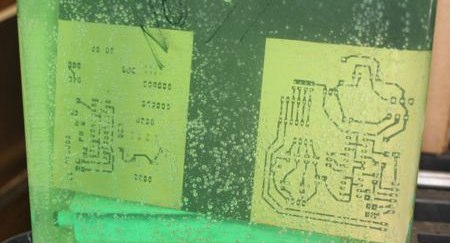
[ladyada] has republished an interesting snippet from the synthDIY mailing list. [David Dixon] discusses the actual chemistry behind ferric chloride based home circuit board etching. He concludes that ferric chloride is essentially a ‘one-shot’ oxidant. It can’t be regenerated and can be difficult to dispose of properly. The use of acidified copper chloride is a much better path and becomes more effective with each use, as long as you keep it aerated and top up the acidity from time to time. This etchant solution is actually the result of initially using hydrogen peroxide as an oxidant along with muriatic acid. You can see us using this solution in our etching how-to and while creating the board for our RGB lock. For more information on using hydrogen peroxide, check out [Adam Seychell]’s guide and this Instructable.

Aside: [ladyada] has added the receiver code to the Wattcher project page.