Bitbanged DVI On A Raspberry Pi RP2040 Microcontroller

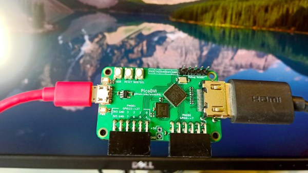
When we first saw the Raspberry Pi Pico and its RP2040 microcontroller last month it was obvious that to be more than just yet another ARM chip it needed something special, and that appeared to be present in the form of its onboard PIO peripherals. We were eagerly awaiting how the community might use them to push the RP2040 capabilities beyond their advertised limits. Now [Luke Wren] provides us with an example, as he pushes an RP2040 to produce a DVI signal suitable to drive an HDMI monitor.

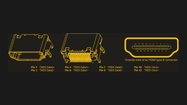
It shouldn’t be a surprise that the chip can be overclocked, however it’s impressive to find that it can reach the 252 MHz necessary to generate the DVI timing. With appropriate terminations it proved possible for the GPIO lines to mimic the differential signalling required by the spec. A PCB with the RP2040 and an HDMI socket was created, also providing a couple of PMOD connectors for expansion. All code and software can be found in a GitHub repository.

The result is a usable DVI output which though it is a relatively low resolution 640×480 pixels at 60 Hz is still a major advance over the usual composite video provided by microcontroller projects. With composite support on monitors becoming a legacy item it’s a welcome sight to see an accessible path to an HDMI or DVI output without using an FPGA.

Thanks [BaldPower] for the tip.

An Open Source HDMI Implementation For FPGAs

With some clever hacks and fast IO work, it’s possible to get your average garden-variety microcontroller to output some form of video. Old analog standards like composite and VGA are just slow enough that it’s possible to bitbash one’s way to success. If you’re serious about video work, however, you’ll want something more capable. For those use cases, [purisame]’s got what you need – an open source HDMI implementation for FPGAs.

Unlike other free and open source projects in this space, [purisame] has eschewed simply outputting compatible DVI signals on the port. This implementation is pure HDMI 1.4b, enabling the extended capabilities this brings, like combined video and audio streams. Thus far, it’s been tested on Xilinx and Altera platforms, though it may be compatible with Lattice, too.

In addition to the code, [purisame] breaks down options for those looking at going into production with an HDMI device. Licencing the technology for sale can be a fraught area, so a lawyer is recommended if you’re heading to market. Oh, and funnily enough, if your really do want to do HDMI on an Arduino, there’s a shield for that, too. Natch!

FPGA Makes ASCII Video

Human beings like pictures which is probably why there’s the old adage “A picture’s worth a thousand words.” We take computer graphic output for granted now, but even in the earliest days for Teletypes and line printers, there was artwork made from characters ranging from Snoopy to Spock. [Wenting Z] continues the tradition by creating an FPGA that converts VGA video to ASCII art and outputs it via DVI.

The device uses a Xilinx Virtex device and uses about 500 LUT (look up tables) which is not much at all. You can see a video (that includes an overlay of the source video) of the device in action below.

In fact, we think of art like this as a computer phenomenon, but [Flora Stacey] created a butterfly on a typewriter in 1898 and ham radio operators were doing art using paper tape for the last half of the twentieth century. Even before that, In 1865, Alice in Wonderland had a certain passage that was typeset to suggest a mouse’s tail. Perhaps the pinnacle is the famous ASCII version of Star Wars.

This is decidedly less mechanical than some of the other ASCII art projects we’ve seen. If you have a taste for more text art, have a look at some other examples, including a very old advertisement that uses character art.

Continue reading “FPGA Makes ASCII Video”

Raspberry Pi Housed Inside A Computer Monitor

rpi-inside-a-computer-monitor

Behold, something we’ve always wanted. [Matthieu] mounted his Raspberry Pi board inside of a computer monitor. His work makes for the cheapest smart-TV modification we can possibly think of.

The image above shows the monitor’s driver board on the left, with the Raspberry Pi mounted on the back plastic cover. [Matthieu] used a short HDMI cable to connect the two. The HDMI connector plugs into the RPi directly. The other end has been cut off and the wires soldered to the DVI pins on the monitor’s PCB. This is not a problem since HDMI and DVI use electrically identical protocols. The one thing missing is audio. But if you were pulling off the same hack with a device that had HDMI (like a television) it would just be a matter of also soldering in the audio connections. While he had his iron hot he also connected a 5V source from the monitor board to the RPi. He completes his hack by cutting a slot in the monitor case to allow access to the SD card.

We’ve long wanted an XBMC computer we could velcro to the back of the TV and the RPi turned out to be just the thing. Now we’ve got to consider cracking open the TV to replicate this internalization hack!

Moving An FPGA Project From VGA To DVI-D

It’s fairly easy to create VGA with an FPGA using a simple R/2R DAC. As [Mike] points out, this requires a lot of IO pins, and many development boards only support 8 bit VGA. Analog VGA is being replaced with DVI-D and HDMI on many devices nowadays, so it would be nice to port projects from VGA to DVI-D.

To address this, he’s come up with a simple DVI-D implementation in VHDL. The result converts RGB and sync data for VGA into DIV-D. Since DVI-D and HDMI both use the same signals for video, this can be connected to either input on a monitor or TV.

This implementation is shown displaying a test pattern on the Pipistrello development board, which features a Spartan 6 LX45 FPGA, but the project was written to be portable to other vendor’s FPGAs. With the right connector and a fast enough clock speed, this project should help move a project from 8 bit VGA to glorious 32 bit color.

Tricking The BeagleBone Into Outputting Video

[FlorianH] wanted to get video out working with his BeagleBone but he just couldn’t figure out how to make the kernel play ball. Then a bit of inspiration struck. He knew that if you plug in the official DVI cape (that’s the BeagleBone word for what you may know as a shield) the kernel automatically starts pumping out the signals he needs. So he figured out a way to spoof the cape and output video.

At boot time the kernel polls the I2C bus to see what’s connected. The DVI cape has an EEPROM which identifies it. Since the data from the EEPROM is available for download [FlorianH] grabbed the data he needed, then used an ATmega32 to stand in for the memory chip. When he got the chip talking to the BeagleBone he was able to detect the video sync signals on his scope and he knew he was in business.

Look closely at the breadboard on the right. We love that SIL breakout board for the ATmega32. Very prototype friendly!

Apple Studio Display Connector Ports

[Warrior_Rocker] pulled off his own Apple Studio Display hack by removing the cable and adding ports. As we saw in Wednesday’s post, these displays use a cable with a proprietary connector that combines DVI, USB and Power. Instead of altering the cable, [Warrior_Rocker] removed it completely. By wiring up a standard barrel jack for power, a USB type-B socket, and a DVI port, he can now use standard video, power, and USB cables to connect to the monitor.

This project was actually submitted to us on May 25th and we missed it. It’s sad that sometimes tips fall through the cracks, and we’re sorry that we missed this particularly well-executed hack. [Warrior_Rocker] wrote in asking why his project didn’t qualify after seeing the similar post on Wednesday. So please don’t take it personally if your project doesn’t get posted. If you think it fits right in here at Hackaday and haven’t heard anything after two weeks or so, consider sending to us again.