Reverse Engineering Smart Meters, Now With More Fuming Nitric Acid

If you’re lucky, reverse engineering can be a messy business. Sure, there’s something to be said for attacking and characterizing an unknown system and leaving no trace of having been there, but there’s something viscerally satisfying about destroying something to understand it. Especially when homemade fuming nitric acid is involved.

The recipient of such physical and chemical rough love in the video below is a residential electric smart meter, a topic that seems to be endlessly fascinating to [Hash]; this is far from the first time we’ve seen him take a deep dive into these devices. His efforts are usually a little less destructive, though, and his write-ups tend to concentrate more on snooping into the radio signals these meters are using to talk back to the utility company.

This time around, [Hash] has decided to share some of his methods for getting at these secrets, including decapping the ICs inside. His method for making fuming nitric acid from stump remover and battery acid is pretty interesting; although the laboratory glassware needed to condense the FNA approaches the cost of just buying the stuff outright, it’s always nice to have the knowledge and the tools to make your own. Just make sure to be careful about it — the fumes are incredibly toxic. Also detailed is a 3D-printable micropositioner, used for examining and photographing acid-decapped ICs under the microscope, which we’d bet would be handy for plenty of other microscopy jobs.

In addition to the decapping stuff, and a little gratuitous destruction with nitric acid, [Hash] takes a look at the comparative anatomy of smart meters. The tamper-proofing features are particularly interesting; who knew these meters have what amounts to the same thing as a pinball machine’s tilt switch onboard?

Continue reading “Reverse Engineering Smart Meters, Now With More Fuming Nitric Acid”

Leaky SMD Electrolytics? Try These Brute Force Removal Methods

When you say “recapping” it conjures up an image of a dusty old chassis with point-to-point wiring with a bunch of dried-out old capacitors or dodgy-looking electrolytics that need replacement. But time marches on, and we’re now at the point where recapping just might mean removing SMD electrolytics from a densely packed PCB. What do you do then?

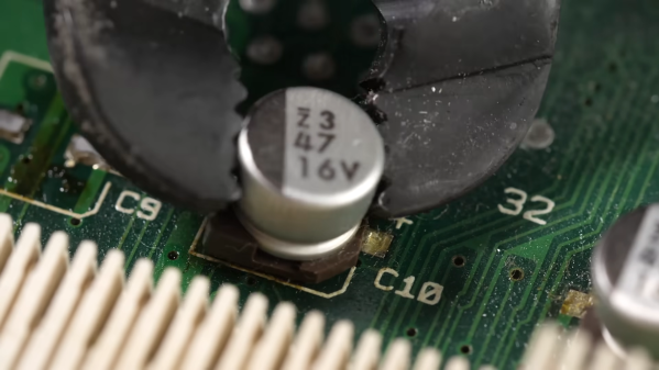
[This Does Not Compute]’s answer to that question is to try a bunch of different techniques and see what works best, and the results may surprise you. Removal of SMD electrolytic caps can be challenging; the big aluminum can sucks a lot of heat away, the leads are usually pretty far apart and partially obscured by the plastic base, and they’re usually stuffed in with a lot of other components, most of which you don’t want to bother. [TDNC] previously used a hot-air rework station and liberally applied Kapton tape and aluminum foil to direct the heat, but that’s tedious and time-consuming. Plus, electrolytics sometimes swell up when heated, expelling their corrosive contents on the PCB in the process.

As brutish as it sounds, the solution might just be as simple as ripping caps off with pliers. This seems extreme, and with agree that the risk of tearing off the pads is pretty high. But then again, both methods seemed to work pretty well, and on multiple boards too. There’s a catch, though — the pliers method works best on caps that have already leaked enough of their electrolyte to weaken the solder joints. Twisting healthier caps off a PCB is likely to end in misery. That’s where brutal method number two comes in: hacking the can off the base with a pair of flush cutters. Once the bulk of the cap is gone, getting the leads off the pad is a simple desoldering job; just don’t forget to clean any released schmoo off the board — and your cutters!

To be fair, [This Does Not Compute] never seems to have really warmed up to destructive removal, so he invested in a pair of hot tweezers for the job, which works really well. But perhaps you’re not sure that you should just reflexively replace old electrolytics on sight. If so, you’re in pretty good company.

Continue reading “Leaky SMD Electrolytics? Try These Brute Force Removal Methods”

Interference Patterns Harnessed For Optical Logic Gates

The basics of digital logic are pretty easy to master, and figuring out how the ones and zeroes flow through various kinds of gates is often an interesting exercise. Taking things down a level and breaking the component AND, OR, and NOR gates down to their underlying analog circuits adds some complexity, but the flow of electrons is still pretty understandable. Substitute all that for photons, though, and you’ll enter a strange world indeed.

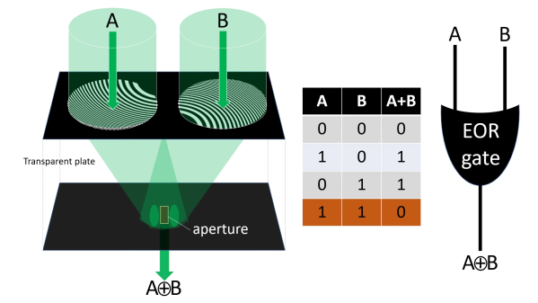
At least that’s our take on [Jeroen Vleggaar]’s latest project, which is making logic gates from purely optical components. As he himself admits in the video below, this isn’t exactly unexplored territory, but his method, which uses constructive and destructive interference, seems not to have been used before. The basic “circuit” consists of a generator, a pair of diffraction patterns etched into a quartz plate, and an evaluator, which is basically a pinhole in another plate positioned to coincide with the common focal point of the generator patterns. An OR gate is formed when the two generators are hit with in-phase monochromatic light. Making the two inputs out of phase by 180° results in an XOR gate, as destructive interference between the two inputs prevents any light from making it out of the evaluator.

Continue reading “Interference Patterns Harnessed For Optical Logic Gates”