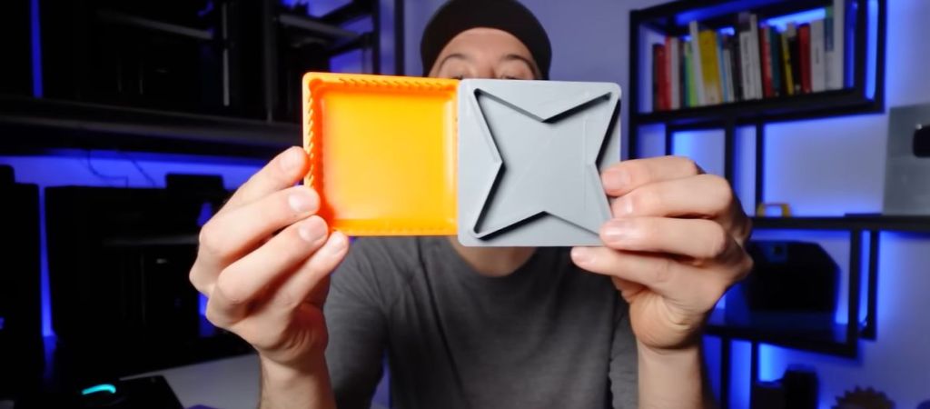
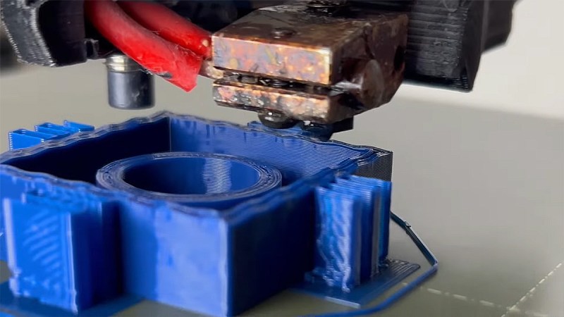
One of the continuing struggles with FDM printing is making sure that parts that should fit together actually do. While adding significant tolerance between parts is an option, often you want to have a friction fit or at least a gap that you cannot drive a truck through. In a video by [Slant 3D] a number of tips and tricks to improve parts design with tolerance in mind are provided.
Starting with the fairly obvious, such as avoiding sharp corners, rounding off edges and using chamfered edges and filets for e.g. lids to make getting started easy, the video then moves into more advanced topics. Material shrinkage is a concern, which is where using thin walls instead of solid blocks of material helps, as does using an appropriate infill type. Another interesting idea is to use a compliant mechanism in the lid to get a friction fit without getting all print parameters just right.
On the opposing side to the lid – or equivalent part – you’d follow many of the same tips, with the addition of e.g. slots that allow for the part to flex somewhat. All of this helps to deal with any variability between prints, with the suggested grip fins at the end of the video being probably the most extreme.
PAHT-CF part printed at 45 degrees, with reinforcing bolt, post-failure. (Credit: Functional Print Friday, YouTube)
The good part about FDM 3D printing is that there are so many different filament types and parameters to choose from. This is also the bad part, as it can often be hard to tell what impact a change has. Fortunately we got destructive testing to provide us with some information here. Case in point [Functional Print Friday] on YouTube recently testing out a few iterations of a replacement part for a car.
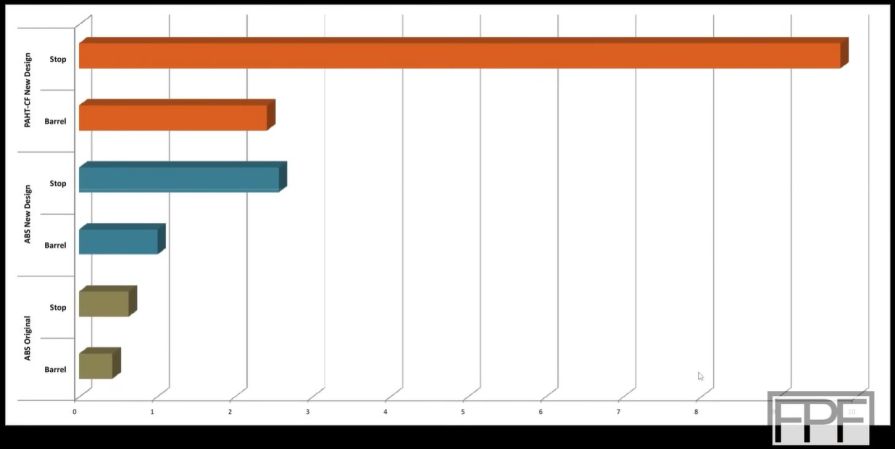
The original part was in ABS, printed horizontally in a Bambu Lab FDM printer, which had a protruding element snapped off while in use. In addition to printing a replacement in carbon fiber-reinforced nylon (PAHT-CF, i.e. PA12 instead of the typical PA6), the part was now also printed at a 45° angle. To compare it with the original ABS filament in a more favorable way, the same part was reprinted at the same angle in ABS.
Another change was to add a machine screw to the stop element of the part, which turned out to make a massive difference. Whereas the original horizontal ABS print failed early and cleanly on layer lines, the angled versions put up much more of a fight, with the machine screw-reinforced stop combined with the PA12 CF filament maxing out the first meter.
The take-away here appears to be that not only angles are good, but that adding a few strategic metal screws can do wonders, even if you’re not using a more exotic filament type.
The Stronghero 3D hybrid PLA PETG filament, with visible PETG core. (Credit: My Tech Fun, YouTube)
Sometimes you see an FDM filament pop up that makes you do a triple-take because it doesn’t seem to make a lot of sense. This is the case with a hybrid PLA/PETG filament by Stronghero 3D that features a PETG core. This filament also intrigued [Dr. Igor Gaspar] who imported a spool from the US to have a poke at it to see why you’d want to combine these two filament materials.
According to the manufacturer, the PLA outside makes up 60% of the filament, with the rest being the PETG core. The PLA is supposed to shield the PETG from moisture, while adding more strength and weather resistance to the PLA after printing. Another interesting aspect is the multi-color look that this creates, and which [Igor]’s prints totally show. Finding the right temperatures for the bed and extruder was a challenge and took multiple tries with the Bambu Lab P1P including bed adhesion troubles.
As for the actual properties of this filament, the layer adhesion test showed it to be significantly worse than plain PLA or PETG when printed at extruder temperatures from 225 °C to 245 °C. When the shear stress is put on the material instead of the layer adhesion, the results are much better, while torque resistance is better than plain PETG. This is a pattern that repeats across impact and other tests, with PETG more brittle. Thermal deformation temperature is, unsurprisingly, between both materials, making this filament mostly a curiosity unless its properties work much better for your use case than a non-hybrid filament.
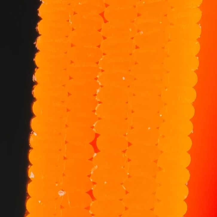
The OrcaSlicer staggered perimeters in an FDM print, after slicing through the model. (Credit: CNC Kitchen)
The idea of staggered (or brick) layers in FDM prints has become very popular the past few years, with now nightly builds of OrcaSlicer featuring the ‘Stagger Perimeters’ option to automate the process, as demonstrated by [Stefan] in a recent CNC Kitchen video. See the relevant OrcaSlicer GitHub thread for the exact details, and to obtain a build with this feature. After installing, slice the model as normal, after enabling this new parameter in the ‘Strength’ tab.
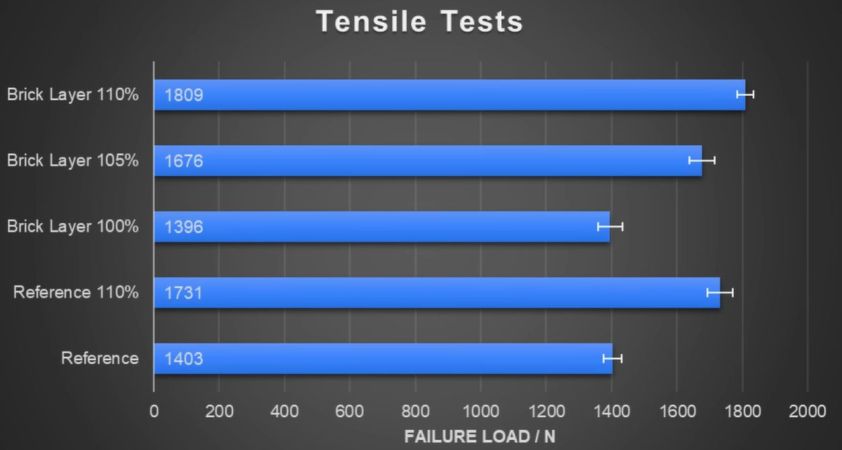
In the video, [Stefan] first tries out a regular and staggered perimeter print without further adjustments. This perhaps surprisingly results in the staggered version breaking before the regular print, which [Stefan] deduces to be the result of increasing voids within the print. After increasing the extrusion rate to 110% to fill up said voids, this does indeed result in the staggered part showing a massive boost in strength.
What’s perhaps more telling is that a similar positive effect is observed when the flow is increased with the non-staggered part, albeit with the staggered part still showing more of a strength increase. This makes it obvious that just staggering layers isn’t enough, but that the flowrate and possibly other parameters have to be adjusted as well to fully realize the potential of brick layers. That said, it’s encouraging to see this moving forward despite questionable patent claims.
Strenghtening FDM prints has been discussed in detail over the last years. Solutions and results vary as each one’s desires differ. Now [TenTech] shares his latest improvements on his post-processing script that he first created around January. This script literally bends your G-code to its will – using non-planar, interlocking sine wave deformations in both infill and walls. It’s now open-source, and plugs right into your slicer of choice: PrusaSlicer, OrcaSlicer, or Bambu Studio. If you’re into pushing your print strength past the limits of layer adhesion, but his former solution wasn’t quite the fit for your printer, try this improvement.
Traditional Fused Deposition Modeling (FDM) prints break along layer lines. What makes this script exciting is that it lets you introduce alternating sine wave paths between wall loops, removing clean break points and encouraging interlayer grip. Think of it as organic layer interlocking – without switching to resin or fiber reinforcement. You can tweak amplitude, frequency, and direction per feature. In fact, the deformation even fades between solid layers, allowing smoother transitions. Structural tinkering at its finest, not just a cosmetic gimmick.
This thing comes without needing a custom slicer. No firmware mods. Just Python, a little G-code, and a lot of curious minds. [TenTech] is still looking for real-world strength tests, so if you’ve got a test rig and some engineering curiosity, this is your call to arms.
Do you like high-detail 3D models intended for resin printing, but wish you could more easily print them on a filament-based FDM printer? Good news, because [Jacob] of Painted4Combat shared a tool he created to make 3D models meant for resin printers — the kind popular with tabletop gamers — easier to port to FDM. It comes in the form of a Blender add-on called Resin2FDM. Intrigued, but wary of your own lack of experience with Blender? No problem, because he also made a video that walks you through the whole thing step-by-step.
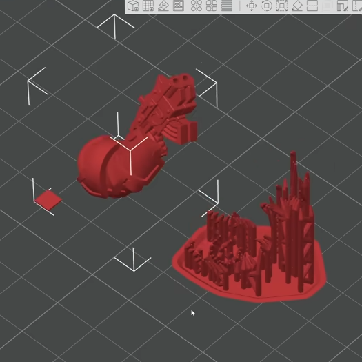
Resin2FDM separates the model from the support structure, then converts the support structure to be FDM-friendly.
3D models intended for resin printing aren’t actually any different, format-wise, from models intended for FDM printers. The differences all come down to the features of the model and how well the printer can execute them. Resin printing is very different from FDM, so printing a model on the “wrong” type of printer will often have disappointing results. Let’s look at why that is, to better understand what makes [Jacob]’s tool so useful.
Rafts and a forest of thin tree-like supports are common in resin printing. In the tabletop gaming scene, many models come pre-supported for convenience. A fair bit of work goes into optimizing the orientation of everything for best printed results, but the benefits don’t carry directly over to FDM.
For one thing, supports for resin prints are usually too small for an FDM printer to properly execute — they tend to be very thin and very tall, which is probably the least favorable shape for FDM printing. In addition, contact points where each support tapers down to a small point that connects to the model are especially troublesome; FDM slicer software will often simply consider those features too small to bother trying to print. Supports that work on a resin printer tend to be too small or too weak to be effective on FDM, even with a 0.2 mm nozzle.
To solve this, [Jacob]’s tool allows one to separate the model itself from the support structure. Once that is done, the tool further allows one to tweak the nest of supports, thickening them up just enough to successfully print on an FDM printer, while leaving the main model unchanged. The result is a support structure that prints well via FDM, allowing the model itself to come out nicely, with a minimum of alterations to the original.
Resin2FDM is available in two versions, the Lite version is free and an advanced version with more features is available to [Jacob]’s Patreon subscribers. The video (embedded below) covers everything from installation to use, and includes some general tips for best results. Check it out if you’re interested in how [Jacob] solved this problem, and keep it in mind for the next time you run across a pre-supported model intended for resin printing that you wish you could print with FDM.
The CNT coating between the layers is heated with microwaves to locally anneal. (Credit: Sweeney et al., Science Adv., 2017)
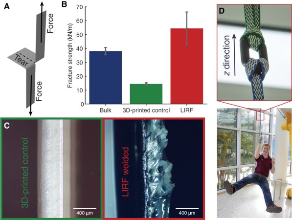
Layer adhesion is one of the weak points with FDM 3D printing, with annealing often recommended as a post-processing step. An interestingly creative method for this was published in Science Advances back in 2017, featuring the work of researchers at Texas A&M University and citing previous work by other teams. In the paper by [Charles B. Sweeney] et al, they describe how they coated PLA filament with carbon nanotubes (CNTs), resulting in this CNT being distributed primarily between the individual layers of polymer.
This is useful because CNTs are quite sensitive to microwave radiation, resulting in the conversion to thermal energy, i.e. heat. Compared to traditional annealing where the entire part is placed into an oven or similar, this microwave-based heating – or locally induced RF (LIRF) as they call this method – localizes the heat to the interface between two layers.
The advantages of this approach are that it doesn’t change the dimensions of the part noticeably, it’s faster and more efficient, and the annealing between layers approaches the strength of traditional manufacturing. Unfortunately not too much seems to have happened with this approach since then, but considering that both CNTs (single & double-walled) and microwaves are readily available, there’s not much standing in the way of replicating these results.