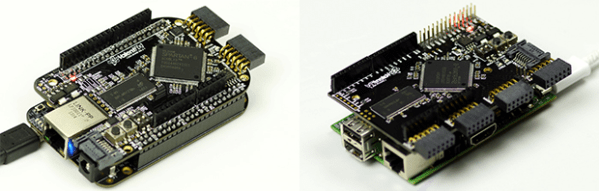
Laptop LCD Resurrection Gets Some Clean Packaging

We love to see derivative works that take a great hack and make it even better. This LCD Laptop resurrection project is an excellent example. [Alex] took the work seen on this other FPGA LCD driver and delivered a leap forward on the final hardware packaging.

The link at the top drops you into the second page of [Alex’s] project thread. But if you go back to the beginning you’ll see the protoboard and spaghetti wiring which started off the process. Obviously if he plans to use this for a length of time it needs to be fortified or he’ll be cracking it open and grabbing a soldering iron again before long. But rather than just tidying up he ended up spinning his own circuit boards that make the screen look like it was manufactured to be used in this way.

He was able to mount the add-on board inside the LCD bezel, cutting out a space for the HDMI connector, barrel jack, trimpot, and the head of the inductor which was just a bit too large to fit inside. The trimpot allows him to adjust the LCD brightness. As far as we can tell the HDMI connector is just an easy way for him to deliver the drive signals from the Papilio board (FPGA) to the screen.

Exploring The Mandelbrot Set In Real Time

The Mandelbrot set – the fractal ‘snowman turned on its side’ seen above – has graced the covers of magazines, journals, and has even been exhibited in art galleries. An impressive feat for what is nothing more than a mathematical function, and has become something of an obsession for [Chiaki Nakajima].

Even on modern computers, generating an image of a portion of the Mandelbrot set takes a good bit of time. When [Chiaki] discovered this fractal in the mid-1980s, the computers of the day took hours to generate a single, low-resolution image. Real-time zooming and scrolling was impossible but [Chiaki] made the best of what he had on hand and built Pyxis, a Mandelbrot set generator made entirely out of TTL logic chips (Google Translate here).

The original Pyxis connected to a desktop computer via a breakout box. while a special program toggled the bits and registers inside the Pyxis to generate pictures of the Mandelbrot set a thousand times faster than the CPUs of the day could muster.

Time marches on, and the original logic chip Pyxis is can be easily surpassed by even the slowest netbooks. There is, however, another way to build a hardware Mandelbrot set generator: FPGAs.

A few years ago, [Chiaki] began work on the Pyxis2010 (translation), an FPGA-based Mandelbrot set generator able to dynamically zoom and pan around the world’s most popular fractal. Built around an Altera Cyclone III FPGA he picked up from Digikey for $600 (no, not a dev board, just a bare chip), [Chiaki] began deadbugging his circuit directly onto the pins of the hugely expensive FPGA. A man with a steady hand and no fear if there ever was one.

Instead of connecting his Mandelbrot generator to a computer and using it as a co-processor, [Chiaki] decided he wanted something more portable. He found an old Sony PSP, removed the LCD screen, and integrated it into his circuit. After a careful bit of dremeling and fabrication, [Chiaki] had a hand-held Mandelbrot generator that is able to display images of the world’s most famous fractal faster than any desktop computer.

It goes without saying this build is incredible. The technical skill to build an insanely fast Mandelbrot generator on an FPGA is astonishing, but basing it off a logic-chip based build reaches into the realm of godliness. You can check out a video of this amazing build after the break.

Props to [Ian Finder] for sending this one in.

Continue reading “Exploring The Mandelbrot Set In Real Time”

Storing User Data On Your FPGA

We’ve seen FPGAs used to recreate everything from classic arcade games to ancient computers, but with each of these builds a common problem arises. Once you’ve got the hardware emulated on an FPGA, you’ve also got to get the ROMs into the project as well. In a very interesting hack, [Mike] figured out that the serial Flash chip that stores the FPGA settings has a lot of space free, so why not store user data there?

[Mike] got the idea from seeing a recreation of the classic BombJack arcade game we featured last month. In that build, [Alex] needed to store 112Kb of game data stored in 16 ROM chips. Unfortunately, [Alex]’s FPGA only had space for 40Kb of data. After realizing his FPGA had a 512Kb SRAM chip, [Alex] decided to put all the sprites, sounds, and levels of BombJack in the SRAM.

Impressed with [Alex]’s build, [Mike] set to work generalizing the hack to work with other projects. [Mike] notes that only a few FPGA boards are capable of storing user data next to the  configuration bitstream; the hack is impossible on the Digilent Basys2 board, but it works wonderfully on a Papilio One 250K.

As a very cool build that makes FPGA-related builds even easier, we’ve got to tip our hat to [Mike] for writing up a great tutorial.

LVDS On An FPGA Could Make It Possible To Reuse Laptops LCDs And The Like

Search around the Internet and you’ll find a landfill of forum threads asking how to drive the LCD screen from a dead laptop. The answer is always that there is just no way to do it. That’s because most of them use a Low-Voltage Differential Signalling protocol that just isn’t available through the hardware used in hobby projects. But the appearance of this board could signal that things are about to change. We don’t want to get your hopes up too much. This isn’t an open source project, but it is a piece of hardware that can make LVDS available for the 8, 16, and 32-bit microcontrollers you’re used to working with.

It’s a derivative of a project [Thomas Jespersen] worked on for a customer. It uses an FPGA to implement the LVDS standard used by high-pixel-count LCD displays. It contains enough memory for a full frame-buffer, and includes a Motorola-8080 communication standard. [Thomas] gives a full description of how the setup works in the video after the break. Demonstrations start about 7:30 into the video with an STM32 F4 Discovery board driving the display.

Continue reading “LVDS On An FPGA Could Make It Possible To Reuse Laptops LCDs And The Like”

Homebrew FPGAs

Homebrew CPUs made out of logic chips are nothing new, but a homebrew FPGA is another matter entirely. [Joshua] sent in a project he whipped up where he made a single logic cell FPGA.

Despite how complicated and intimidating they are in practice, FPGAs are really very simple. They’re made of thousands of logic blocks capable of transmuting into AND, OR, NAND, and XOR logic gates. These logic blocks are all tied together, and with a somewhat complex hardware design language are capable of becoming a CPU, a micocontroller, or even a video card. Basically, programming a microcontroller tells a chip what to do, while programming an FPGA tells the chip what to be.

To build his single logic block FPGA, [Joshua] used a four-bit multiplexer to hard wire a truth table out of a 74HC174 D-type flip-flop. A bit of Arduino code changes the state of the pins connected to the multiplexer allows for any combination of TRUE and FALSE to be calculated for AND, NAND or XOR logic functions.

Yes, it’s only a single logic block for an FPGA, and if this build were expanded to even a few hundred cells it would be gargantuan. Still, there’s no better way to learn the ins and outs of abstract hardware, so we’ll gladly tip our hat to [Joshua] and his homebrew FPGA.

Using An Undocumented Display With An FPGA

When [Mike] ran across a display on Deal Extreme with 8 seven-segment displays, 8 red/green LEDs, and 8 buttons, he knew it would find a good home in a future project. There was only one problem, though: except for an Arduino library, there was absolutely no documentation available for this display. Wanting to use this display with an FPGA board, [Mike] decided against bit-banging a protocol and ported the C++ code into a hardware implementation.

This Deal Extreme display, the TM1638, features enough seven-segment displays, LEDs and buttons to build something really cool, and surprisingly isn’t terribly hard to interface with a microcontroller. The TM1638 library communicates with the outside world via only three pins and a simple serial connection.

After figuring out what commands are sent to make the display turn LEDs on or off, [Mike] wrote a hardware implementation for his Digilent Nexys2 and Digilent Basys2. Now the display operates on an FPGA just like it does with an Arduino, and is a great tool for debugging HDL code for [Mike]’s FPGA.

Full-color Video On A Spinning POV Display

Watching Big Buck Bunny on a spinning POV display is pretty impressive. Sure, the circular display area cuts off some of the picture, but otherwise it looks fantastic. This POV display is based on a Gumstix board. It runs embedded Linux which makes video playback rather easy. But translating each frame to the round display is another story.

The device is the result of a course project at Telecom ParisTech. [Félix], [Sylvain], and [Jérémy] used an FPGA to do the pixel mapping. This uses an encoder wheel (rather than a traditional hall effect sensor) to ascertain the blade’s position. The sensor that monitors the disc sends quadrature encoded pulses which result in 10-bit position data. The FPGA uses that data to calculate where each LED falls in its arc, then looks up the pixel color for that position. It’s not the largest POV display we’ve seen, but it certainly has the very best RGB resolution by far.

Continue reading “Full-color Video On A Spinning POV Display”