We’re glad we’re not the only hacker-packrats out there! [Voja Antonic] recently stumbled on an EPROM emulator that he’d made way back in 1991. It’s a sweet build, so take your mind back 25 years if you can. Put on “Nevermind” and dig into a nicely done retro project.
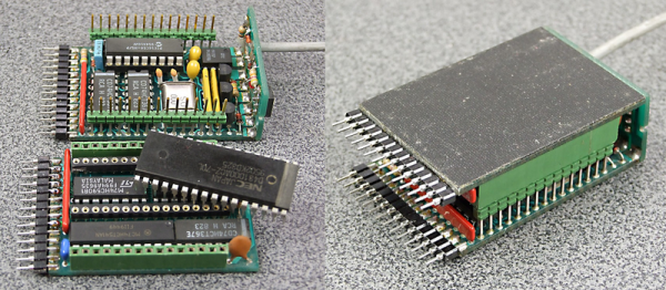
The emulator is basically a PIC 16C54 microcontroller and some memory, with some buffers for input and output. On one side, it’s a plug-in replacement for an EPROM — the flash memory of a bygone era. On the other side, it connects via serial port to a PC. Instead of going through the tedious process of pulling the EPROM, erasing and reprogramming it, this device uploads new code in a jiffy.
No need to emulate ancient EPROMS? You should still check out this build — the mechanics are great! We love the serial-port backplane that is soldered on at a 90° angle. The joint is a card-edge connector electrically, but also into a nice little box, reminiscent of [Voja]’s other FR4 fabrication tricks. The drilled hole with the LED poking out is classy. We’re never going to make an EPROM emulator, but we’re absolutely going to steal some of the fabrication techniques.
[Voja] is a Hackaday contributor, badge-designer, mad hacker, inspired clock-builder, and developer of (then) Yugoslavia’s first DIY PC.