Hackaday Prize Entry: Solving The Shortage Of Walking Robots

The world has a severe lack of robots, and the shortage of walking robots is untenable. We were promised flying cars and fusion reactors, yet here we are, 15 years into the twenty-first century without even a robotic pet spider.

[Radomir]’s entry for The Hackaday Prize aims to fix this bizarre oversight of scientific and technological progress. He’s designed a small, inexpensive, but very well designed quadrupod robot that will put full reverse kinematics on your desk for under $50.

To solve humanity’s glaring lack of walking robots, [Radomir] designed Tote, a four-legged robot whose chassis is mostly composed of only 9 gram servos. There are twelve servos in total, three on each of its four legs. It’s an extension of his earlier µKubik robot. While the µKubik was powered by Python, the Tote is all Arduinofied, calculating the trajectories of each leg dozens of times a second with an Arduino Pro Mini.

This isn’t the only walking robot kit on hackaday.io; last year, [The Big One] created Stubby the Teaching Hexapod. Even though Stubby featured six legs, it’s still remarkably similar to Tote; 9 gram servos provide all the locomotion, and all the software is running on a relatively small ATMega microcontroller. Both are great introductions to walking robots, and both bots will surely be capable and just rulers of mankind after the robot apocalypse.


The 2015 Hackaday Prize is sponsored by:

psp media player

PSP Media Player For The Home Workshop

It’s a common occurrence that some items we buy become more and more obsolete as time passes. This is especially true for electronics gear since technology progresses so quickly. [Rochefoucauld] had a PSP that he didn’t use anymore and was trying to figure out what to do with it. Then one day in his basement shop while yearning for some tunes, it hit him: use the PSP as a media player.

The PSP is actually not modified and uses the standard media player, it is the project’s execution that is interesting. Some old computer speakers were taken apart to harvest the amplifier. [Rochefoucauld] had an external hard drive that broke so he scavenged the sleek looking case and mounted the amplifier PCB inside. The speaker outputs were routed to terminal blocks mounted on the back of the case. The PSP now resides on a mount made out of a floor joist hanging bracket from the hardware store. The PSP and amplifier share the same power supply and master power switch. The whole unit powers a pair of bookshelf speakers.

In the end, [Rochefoucauld] solved his lack-of-music problem with parts he had kicking around and is also now making use of his PSP that was otherwise collecting dust. For more non-traditional uses for PSPs, check out this status monitor or this extended display.

Pendulum MIDI Controller Really Swings

Once in a while, we see a project that makes us want to stop whatever we’re doing and build our own version of it. This time, it’s Modulum, a pendulum-based MIDI controller. It’s exactly what it sounds like. The swinging pendulum acts as a low-frequency oscillator. In the demo video configuration, you can hear it add a watery, dreamlike quality, sort of like a lap steel guitar on LSD.

The pendulum’s motion is detected by four pieces of stretchy, conductive cord. These are wired to an Arduino Nano in a voltage divider fashion. [Evan and Kirk] used the Maxuino library to determine x and y mapping of possible pendular positions as well as perform the necessary MIDI processing. Get your groove on after the break, and check out some of the many other fantastic MIDI controllers we’ve had the pleasure of covering.

Continue reading “Pendulum MIDI Controller Really Swings”

Flat Pack Lamp

Flat Pack Elastic Band Lamp Is A Thing Of Beauty

[Matt] was looking for a project for his senior industrial design studio at Wentworth Institute of Technology. He ended up designing a clever lamp that can be flat packed. [Matt] started by drawing out designs on paper. He really liked the idea of combining curves with straight lines, but he wanted to translate his two-dimensional drawings into a three-dimensional shape.

zOz0ys6 - ImgurHaving access to a laser cutter made the job much easier than it could have been and allowed [Matt] to go through many designs for the lamp frame. The two main pieces were cut from acrylic and include mounting pegs for the elastic bands. The two plastic pieces are designed to slot together, forming a sort of diamond shape.

The final version of the lamp required that the elastic bands had holes punched in them for mounting. The holes were placed over the small pegs to keep the bands in place. [Matt] used 3/4″ industrial elastic bands for this project. He then used a 120V 15W candelabra light bulb to illuminate the lamp. The final design is not only beautiful, but it can be flat packed and manufactured inexpensively.

If you want more inspiration for artistically designed lamps check out this one that uses the corrugation in cardboards as a shade pattern.

[via reddit]

Laser Cutter Exhaust Interlock Is Silly, Educational, Useful

If there’s one maker space that has an excess of mad scientist type hackers, it has to be LVL1 in Louisville, KY. They sure do a lot of crazy stuff, like this simple device to defeat the laser cutter smoke monster. Nobody got the memo about the “simple” part. Instead they created a functional, educational and aesthetically pleasing element for the hackerspace.

LVL1 has a large format laser cutter. Laser cutters emit nasty smoke. Said smoke needs to be vented outside. To do so, it needs to pass through a scrubber/filter so the neighbouring Pigs don’t complain. So they installed a larger, better filter. The Pigs are happy, until the filter gets clogged and the smoke monster decides to escape. Next they install a pressure switch which disables the laser when the filter gets clogged. Laser cutters have a myriad of safety interlocks, so quite often, it isn’t apparent which one caused it to trip. Hence, the Laser Cutter Enable Module – LCEM.

The simple part was to install an indicator that lights up when the pressure switch is enabled, and off when not. But when it’s off, it isn’t clear if the pressure switch is off, or the indicator has failed. Simple, just install a bi-color LED – Red for off, Green for On. But then what about color blind folks who cannot tell the two colors apart? So, finally, two LED’s with clearly labelled text marking them as Enabled and Disabled.

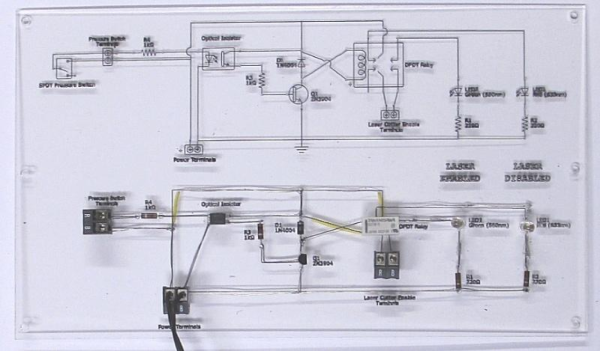
A simple (this time for real) circuit was finally agreed upon. The SPDT contacts of the pressure switch drive the LED in an optoisolator. Its output drives a DPDT relay via a transistor. One set of contacts light up the two indicator LED’s and the other set of contacts goes to the laser cutter enable contacts. Of course, the optoisolator is totally redundant and over kill too – it’s input LED shares the same power supply as the output transistor! Remember the missing memo?

It was time to assemble the circuit. This is where the mad scientist dudes got really creative. On one half of a piece of acrylic, the schematic diagram was etched using the laser. This ensures n00bs get some education. And the remaining half had the circuit laid out in old-skool wire wrap fashion. Holes were drilled and connections were drawn (using the laser, of course) for the various components. Parts were inserted, and wires were soldered to make the connections. The result is what they call the PCB/Mounting Plate/Educational Schematic/Acrylic thing. Of course, exposed connections and wires are no good. So they made a sandwich consisting of a flat acrylic base, and a cut out frame in the middle to accommodate the wire connections and joints. All of this to light up an indicator. Because.

Thanks [JAC_101] from LVL1 for sending in this tip.

If you want to read more about LVL1 shenanigans, check out this post about their Rocketry group, or this post when Hackaday visited LVL1.
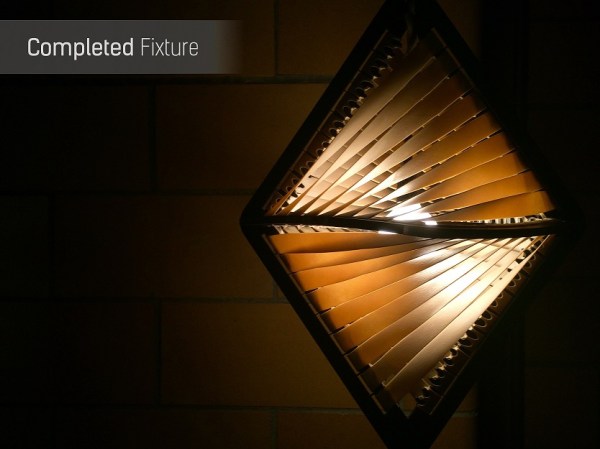
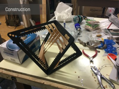
How To Build Beautiful Enclosures From FR4 — Aka PCBs

Most hobbyists say that it is easier to build a functional prototype of an electronic device, than to make the enclosure for it. You could say that there are a lot of ready-made enclosures on the market, but they are never exactly what you need. You could also use a 3D printer to build a custom enclosure, but high-end 3D printers are too expensive, and the cheaper ones produce housings which are often not robust enough, and also require a lot of additional treatment.

Another way is to build the enclosure out of FR4, a material which is commonly used in PCB production. Such enclosures are low-cost, with thin walls but yet very strong, nice looking, pleasant to the touch and have excellent thermal and moisture stability. FR4 offers some more possibilities – efficient wiring with no wires inside the housing, integrated UHF or SHF antennas or RFID coils, capacitive switches, electrical shielding, selective semi-transparency, water or air tightness, and even integration of complex mechanical assemblies.

Here I shall explain the process of building those “magic” enclosures. It is based on nearly fifty years of personal experience and more than a hundred enclosures, built for most of my projects. Here are two examples – this case for a hardware password manager is just a few centimeters long, while the other one (protective transportation cover for my son’s synthesizer) measures 125cm (about 49 inches), and yet both of them are strong enough to withstand a grown man standing on top of them.

The global approach is simple – you take the sheet of single-sided copper clad FR4, cut it and solder the parts together. That sounds simple, but there are a lot of details which should be met if you want to get top results. Please read about them carefully. You might be tempted to skip some of the steps described here, but if you do so, you will most likely end up being disappointed with the results.

Continue reading “How To Build Beautiful Enclosures From FR4 — Aka PCBs”

ShakeIt – An Interactive Light Game

Learning becomes interesting when you make it fun, interactive and entertaining. [Arkadi] built ShakeIt – an interactive game for the Mini MakerFaire in Jerusalem to demonstrate to kids and grownups how light colors are mixed. It is a follow up to his earlier project – Smart juggling balls which we featured earlier.

The juggling balls consist of a 6 dof sensor (MPU 6050), a micro controller, transmitter (NRF24L01+), some addressable RGB LED’s and a LiPo battery. An external magnet activates a reed switch inside the balls and triggers them in to action. The ShakeIt light fixture consists of an Arduino Nano clone, NRF24L01+ with SMA Antenna, buck converter, 74 addressable RGB LED’s, and a bluetooth module. The bluetooth module connects to a smartphone app.

[Arkadi] starts out by handing three juggling balls, each with a predefined color (Red, Green, Blue). When the ball is shaken, the light inside the ball becomes stronger. The ShakeIt light fixture is used as a mixer. It communicates with the balls and receives the value of how strong the light inside each of the smart balls is, mixing them up, and generating the mixed color.

The fun starts when the interactive game mode is enabled. Instead of just mixing the light, the Light fixture generates patterns based on how strong the balls are shaken. At first the light fixture shows all three colors filling up the central ball. The three contenders then fight out to get their color to fill up the sphere completely until only one color remains and the winner is declared.

The kids might be learning some color theory here, but it seems the adults are having a “ball” playing the crazy game. If you’d like to build your own shoulder dislocating ShakeIt game, head over to [Arkadi]’s github repository for the ShakeIt and the Juggling Balls. Check the video below to see the adults having fun.

Continue reading “ShakeIt – An Interactive Light Game”