Training Fish To Feed Themselves

We’ve featured quite a few aquarium and fish feeder hacks on our blog. [RoboPandaPDX] thought of taking it up a notch and make an interactive fish feeder. He built a Fish feeder that train’s them to feed themselves.

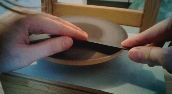
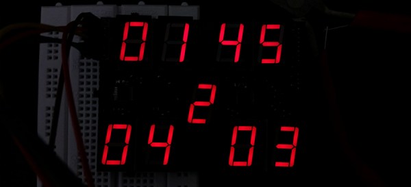
A copper bar hangs from the middle of a metal cylinder – much like a bell. The end of the bar has a fish lure. When a fish pushes the lure, the copper bar touches the metal cylinder and  closes the circuit. This signal goes to an Arduino. To catch the attention of the fishes and to “teach” them, an RGB LED is used. The fish need to figure out that the feeder will dispense food only when the LED is ON and the Lure is pushed. If the fish figure that out, and push the lure when the LED is on, a servo is activated which pushes the feeder to deliver 1 unit of fish food. While at it, he added a couple of bells and whistles. A buzzer to indicate when the Lure switch is closed and a 2 line LCD shows how many times the switch has been activated and how long the program has been running.

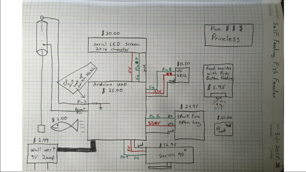
A Sparkfun  open logger stores the hit count and the minutes and seconds of the hit for data analysis later on. The good news is that it seems to be working. The current code activates the feeder for 30 to 60 minutes every day, which is indicated by the LED. At the end of 9 days,  [RoboPandaPDX] found that the goldfish would hit the Lure when the LED turned on, and then turn around to face where the feeder would dispense food in to the tank. His next plan is to put up some obstacles along the path to see if the fish learn some new tricks. His schematic looks a little iffy (the Lure switch is connected to the RST pin of the Arduino), and it seems he cannot remember why he ever did that. He’s happy that it works though, but we’re sure that’s not the right way to wire it up.

[RoboPandaPDX] is looking for suggestions on improving his interactive feeder, so if you have any, do add them in the comments below.

If you need some more fish feeder ideas, check out this and this that we blogged about earlier.

Hackaday Retro Edition: Remaking The PDP 8/I With A Raspberry Pi

[Oscar] really likes the PDP-8s, with the extremely old school PDP-8/I being his favorite. If you haven’t checked the price on these recently, getting a real PDP-8/I is nigh impossible. However, after assembling a KIM-1 clone kit, an idea struck: what about building a modern PDP-8/I replica that looks like the real thing, but is powered by modern hardware. This would be fairly cheap to build, and has the added bonus of not weighing several hundred pounds.

The PiDP-8 is [Oscar]’s project to replicate the hardware of the 8/I in a modern format. Instead of hundreds of Flip Chips, this PDP-8 is powered by a Raspberry Pi running the SIMH emulator. The 40-pin GPIO connector on the Pi is broken out to 92 LEDs and 26 toggle switches on a large PCB. This setup gets [Oscar] a reasonable facsimile of the PDP-8/I, but he’s also going for looks too. He created an acrylic panel with artwork copied from an original 8/I  that mounts to the PCB and gives the entire project that beautiful late 60s / early 70s brown with harvest gold accent color scheme.

Since this emulated PDP-8/I is running on entirely new hardware, it doesn’t make much sense to haul out disk drives as big as a small child, tape drives, and paper tape readers. Instead, [Oscar] is putting everything on USB sticks. It’s a great solution to the problem of moving around files that are a few kilowords in size.

vt100normal
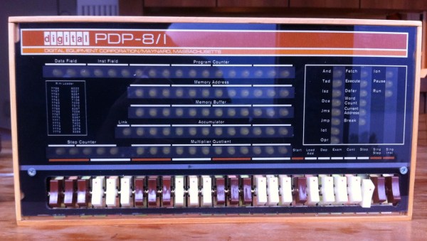
[Oscar] says he’ll be bringing his PiDP to the Vintage Computer Festival East X in Wall, NJ, April 17-19. We’ll be there, and I’ve already offered [Oscar] the use of a VT-100 terminal. If you’re in the area, you should come to this event. It’s guaranteed to be an awesome event and you’re sure to have a great time. Since this is the 50th anniversary of the introduction of the PDP-8, there will be a half-dozen original PDP-8s set up, including a newly refurbished Straight-8 that came out of the RESISTORS.

Oh, if anyone knows how to connect a Pi to a VT100 (technically a 103), leave a note in the comments. Does it need the RTS/CTS?

circuit boards

Control Stuff With Your Muscles

[David Nghiem] has been working with circuitry designed to read signals from muscles for many years. After some bad luck with a start-up company, he didn’t give up and kept researching his idea. He has decided to share his innovations with the hacker community in the form of a wearable suit that reads muscle signals.

It turns out that when you flex a muscle, it gives off a signal called a Surface ElectroMyographic signal, or SEMG for short. [David] is using an Arduino, digital potentiometer and a bunch of op amps to read the SEMG signals. LEDs are used to display the signal levels.

The history behind [David’s] project dates back to the late twentieth century, which he eloquently points out – “Holy crap that was a long time ago”. He worked with the MIT Aero Astro Lab and the Boston University Neuromuscular Research Center where he worked on a robotic arm for astronauts. The idea being to apply an opposing force to the arm to help prevent muscle deterioration.

Be sure to check out [David’s] extensive and well documented work, along with the several videos showing his projects at various stages of completion. If this gives you the electromyography bug, check out this guide on detecting the signals and an application of the concept for robotic prosthesis.

Continue reading “Control Stuff With Your Muscles”

boom box

Get Blown Away By The Boominator

You have a greater chance of squeezing 5 amps through a 2N2222 than you do remembering the 1980s and not thinking about the legendary ‘boom box’. They could be seen perched on the shoulders of rockers and rappers alike – many sporting the Members Only or red leather jackets. The boom boxes visual characteristics can best be described as a rectangular box with two very large speakers on each end. It is no accident that The Boominator shares these features.

[Jesse van der Zouw] did a good job of showing how he created The Boominator. It has not two, but four 10 inch woofers that delivers 360 degrees of awesomeness at 115dB. The on board battery can sustain it for up to twenty hours, and the project is topped off with some blue LED rings the encircle each speaker.

We’ve seen boom boxes here before, but this is the first with some nice LED accents. Be sure to check out this build and let us know what you might have done differently.

[via Hackaday.io]

Hacklet 39: The Kerbal Way Of Doing Things

Kerbal Space Program is a space flight simulator based on an extremely stupid race of green space frogs that have decided to dedicate all their resources towards the exploration of space. It is a great game, a better space simulator than just about anything except for Orbiter, and the game is extremely moddable. For this edition of the Hacklet, we’re going to be taking a look at some of the mods for KSP you can find over on hackaday.io.

1271491420181365398
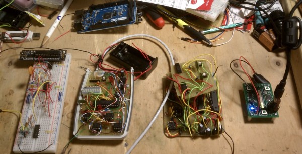
Like most hardware builds for Kerbal Space Program, [lawnmowerlatte] is using a few user-made plugins for
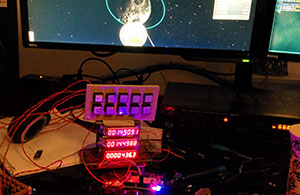
 KAPCOM, a hardware controller and display for KSP. The Telemachus plugin is used to pull data from the game and display that data on a few screens [lawnmower] had sitting around.

There are a few very cool features planned for this build including seven-segment displays, a throttle handle, and neat enclosure.


IMG_20140419_013717[Gabriel] is working on a similar build for KSP. Like the KAPCOM, this one uses the Telemachus plugin, but this one adds three eight-digit, SPI-controlled, seven-segment displays, relegendable buttons, and a Kerbal-insipired frame made out of Meccano.


[Lukas]’ KSP Control Panel is another complicated control system that breaks immersion slightly less than a keyboard. He’s using a Raspberry Pi to talk to the Telemachus server to control every aspect of the craft. From staging to opening up the solar panels, it’s all right there in [Lukas]’ control panel.


You may have noticed a theme with these builds; all of them use the Telemachus plugin for KSP. Even though it’s fairly simple to create plugins for Unity, there really aren’t that many KSP plugins build for these immersive control panels and space flight simulators. Or rather, Telemachus is ‘good enough’. We’d like to see a fully controllable KSP command pod model, just like those guys with 737 flight simulators in their garage. If you have any idea how that could happen, leave a note in the comments.

Bread slicer turned tool sharpener

Sharpening Knives Using A Bread Slicer?

[Joekutz] wrote in to tell us about his very interesting creation — a knife whetting machine, built from an automated bread slicer. Confused? So were we when we read the subject line!

Tired of sharpening knives by hand, [Joe] wanted to speed up the process. He recently saw our post on making a tool sharpening turntable out of a bread maker and figured, why not make one out of a bread slicer? We have no idea how you guys came up with these — finally some real hacks!

First he took apart the bread slicer and salvaged the motor, gears, and some of the electronics. He created an enclosure for it out of some laminate wood he had laying about and created a bearing axle for the disc from an old VCR. To control the speed he’s using a plain old light switch dimmer; not the most efficient but does the trick!

It uses sanding discs you can buy from any hardware store, and as you can see in the following video — it works pretty good according to the paper cutting test!

Continue reading “Sharpening Knives Using A Bread Slicer?”

An Experiment In Shift Registers And Multiplexed LEDs

[Kratz] is working on a WiFi controlled scoreboard, but before building the full-scale version, he thought it would be wise to test out the multiplexing technique for the display. The experiment worked, but unless this scoreboard is for a foosball table, he still has a lot of work ahead of him.

The design of this prototype display is pretty simple, with just two ‘595 shift registers feeding bits to the display. Sixteen NPN transistors are being used to sink and source current to the display. It’s a relatively simple circuit, allowing [Kratz] to fit nine seven-segment displays on a small board with only six wires – ground, two V+ for the logic and LEDs, clock, data, and latch – going to the microcontroller.

There were a few snags in the design; the data is clocked in on a rising edge, but an extra falling edge was required before latching. [Kratz] can’t figure out the reason for this, and it might just be a timing issue.