How can you tell if your software is doing what it’s supposed to? Write some tests and run them every time you change anything. But what if you’re making hardware? [deqing] has your back with the Automatic Hardware Testing rig. And just as you’d expect in the software-only world, you can fire off the system every time you update the firmware in your GitHub.
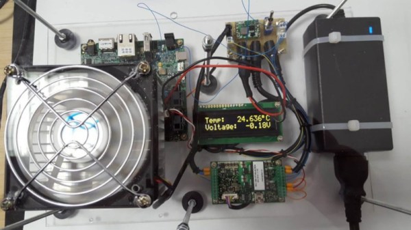
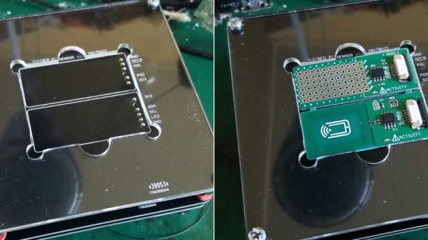
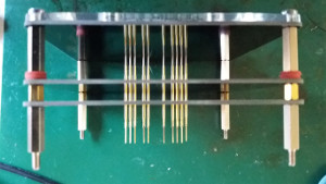
A Raspberry Pi compiles the firmware in question and flashes the device under test. The cool part is the custom rig that simulates button presses and reads the resulting values out. No actual LEDs are blinked, but the test rig looks for voltages on the appropriate pins, and a test passes when the timing is between 0.95 and 1.05 seconds for the highs and lows. Firing this entire procedure off at every git check-in ensures that all the example code is working.
So far, we can only see how the test rig would work with easily simulated peripherals. If your real application involved speaking to a DAC over I2C, for instance, you’d probably want to integrate that into the test rig, but the principle would be the same.
Are any of you doing this kind of mock-up hardware testing on your projects? Is sounds like it could catch bad mistakes before they got out of the house.