Semiconductor Simulator Lets You Play IC Designer

For circuit simulation, we have always been enthralled with the Falstad simulator which is a simple, Spice-like simulator that runs in the browser. [Brandon] has a simulator, too, but it simulates semiconductor devices. With help from [Paul Falstad], that simulator also runs in the browser.

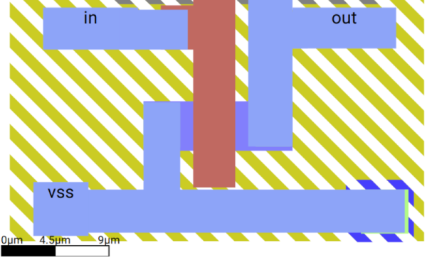
This simulator takes a little thinking and lets you build devices as you might on an IC die. The key is to use the drop-down that initially says “Interact” to select a tool. Then, the drop-down below lets you select what you are drawing, which can be a voltage source, metal, or various materials you find in semiconductor devices, like n-type or a dielectric.

It is a bit tricky, but if you check out the examples first (like this diode), it gets easier. The main page has many examples. You can even build up entire subsystems like a ring oscillator or a DRAM cell.

Designing at this level has its own quirks. For example, in the real world, you think of resistors as something you can use with great precision, and capacitors are often “sloppy.” On an IC substrate, resistors are often the sloppy component. While capacitor values might not be exact, it is very easy to get an extremely precise ratio of two capacitors because the plate size is tightly controlled. This leads to a different mindset than you are used to when designing with discrete components.

Of course, this is just a simulation, so everything can be perfect. If, for some reason, you don’t know about the Falstad simulator, check it out now.

Open Source High Speed SiGe IC Production For Free!

We’ve covered the Tiny Tapeout project a few times on these pages, and while getting your digital IC design out there onto actual silicon for a low cost is super cool, it is still somewhat limited. Now, along comes the German FMD QNC project funding MPW (multi-project wafer) runs not in bog standard Silicon CMOS but Silicon-Germanium bipolar technology. And this is accessible to you and me, of course, provided you have the skills to design in this high-speed analog technology.

The design can be submitted via Github by cloning the IHP-Open-DesignLib repo, adding your design, and issuing a pull request. If your submission passes the correctness checks and is selected, it will be fabricated in-house by the IHP pilot line facility, which means it will take at least four months to complete.  However, there are a few restrictions. The design must be open source, DRC complete (obviously!) and below a somewhat limiting two square millimetres. Bonus points for selecting your project can be had for good documentation and a unique quality, i.e., they shouldn’t have too many similar designs in the project archive. Also, you don’t get to keep the silicon samples, but you may rent them for up to two years for evaluation. In fact, anybody can rent them.  Still, it’s a valuable service to trial a new technique or debug a design and a great way to learn and hone a craft that is difficult to get into by traditional means. Such projects would be an excellent source of verifiable CV experience points we reckon!

If you fancy getting your hands on your own silicon, but bipolar SiGe is a bit of a stretch, look no further than our guide to Tiny Tapeout. But don’t take our word for it—listen to the creator himself!

The Wizard Of Semiconductors

If you have three hours and you want to learn the fundamentals of semiconductors, [Tiny Tapeout] has something for you: An introduction to SiliWiz. You’ll also need the SiliWiz software (or use it online), which resembles the kind of tools that chip designers use but is meant for students to use as a learning tool

Using SiliWiz, you create layers on a virtual device, and you can use Spice to view the results. The tutorial is meant to be high-level and is suggested for students aged 14 or over (but we liked it and we are quite a bit older than that). Some more advanced material is also available at the same site.

Continue reading “The Wizard Of Semiconductors”