Button Debouncing With Smart Interrupts

Debouncing button or switch inputs on microcontrollers can be a challenging problem for those first starting to program these devices. Part of the reason for this difficulty is that real-world buttons don’t behave like the idealized textbook components we first learn about, and therefore need special consideration to operate like one would expect. There are simple ways to debounce inputs like adding a delay after a button is pressed, but for more efficient use of computer resources as well as adding some other capabilities to inputs you might want to look at this interrupt service routine (ISR) method from [Lee] aka [stockvu].

The strategy with this debounce method is not simply to use a single ISR for the button input, but to activate a second timer-based ISR at that time that runs at a certain interval which timestamps any button press and checks the amount of time the button has been active. If it’s under a certain threshold the ISR assumes it’s caused by bounce and blocks the bounce. If the timestamp ages past another longer threshold it knows the button has been released. This method allows on-the-fly adaptation between long button presses and rapid button presses and is capable of debouncing both types.

For those wanting to try this out, [stockyu] has included some example Arduino code for others to use. It’s an interesting take on a solution for a common problem, and puts very little load on the microcontroller. There are about as many ways to debounce inputs as there are microcontroller platforms, though, and you can even use a 555 timer to get this job done which frees up 100% of the microcontroller’s CPU.

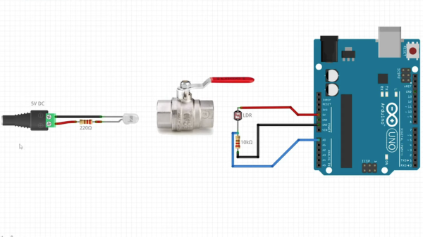
A diagram showing an LED on the left, a lever-style plumbing valve in the center, and an Arduino Uno on the right.

Plumbing Valves As Heavy Duty Analog Inputs

Input devices that can handle rough and tumble environments aren’t nearly as varied as their more fragile siblings. [Alastair Aitchison] has devised a brilliant way of detecting inputs from plumbing valves that opens up another option. (YouTube) [via Arduino Blog]

While [Aitchison] could’ve run the plumbing valves with water inside and detected flow, he decided the more elegant solution would be to use photosensors and an LED to simplify the system. This avoids the added cost of a pump and flow sensors as well as the questionable proposition of mixing electronics and water. By analyzing the change in light intensity as the valve closes or opens, you can take input for a range of values or set a threshold for an on/off condition.

[Aitchison] designed these for an escape room, but we can see them being great for museums, amusement parks, or even for (train) simulators. He says one of the main reasons he picked plumbing valves was for their aesthetics. Industrial switches and arcade buttons have their place, but certainly aren’t the best fit in some situations, especially if you’re going for a period feel. Plus, since the sensor itself doesn’t have any moving parts, these analog inputs will be easy to repair should anything happen to the valve itself.

If you’re looking for more unusual inputs, check out the winners of our Odd Inputs and Peculiar Peripherals contest or this typewriter that runs Linux.

Continue reading “Plumbing Valves As Heavy Duty Analog Inputs”

A Self-Expanding PWM Driver

For smaller microcontrollers, having enough outputs for the job is sometimes a challenge. A common solution is to do some sort of multiplexing with the available outputs or perhaps something more advanced such as Charlieplexing, but another good option is to use a specialized driver board. What’s even better is if you can daisy chain driver boards to get even more outputs.

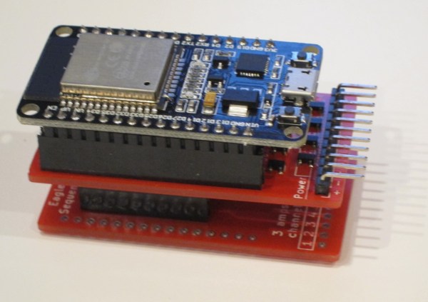
[Eric] has been working on a 16 channel LED project but first wanted to build a driver board with 8 channels. Before building a full 16 channel version he realized that he could take the same 8 channel board, make a mirror image of it, and attach it underneath the first board with headers in order to double the number of channels available. Without having to build a separate 16-channel board, this shortcut saved [Eric] some time and a great deal of effort.

This is a great example of working smarter, not harder. Each of the 8 or 16 channels has full PWM support as well to support PWM dimming, and a similar board could be built for motor control as well. It’s a good illustration of how good design can end up working for you as well. And if you need even more outputs, Charlieplexing is one way to get them.

Continue reading “A Self-Expanding PWM Driver”