Doubling Down On A Big LED Display

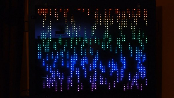
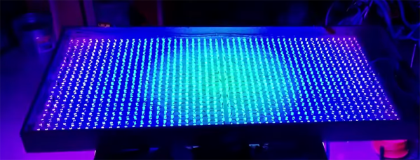
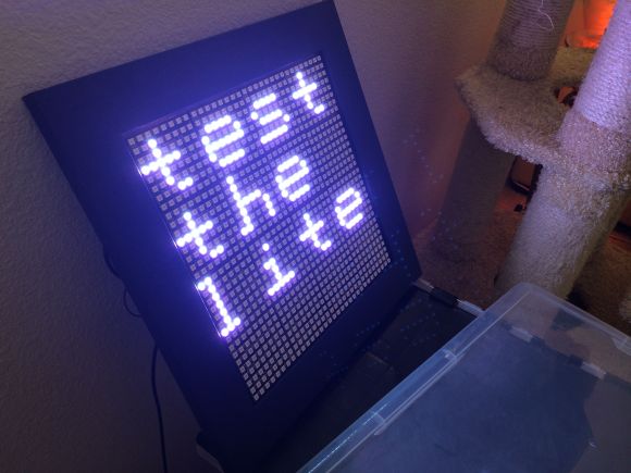
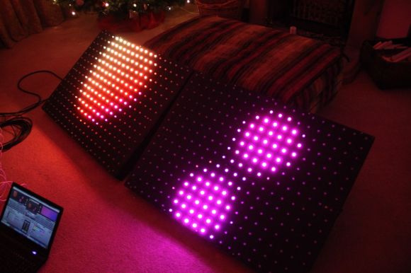
Last year at the 2014 NC Maker Faire, Manical Labs brought a large LED display. Blinking LEDs and pixel animations are always welcome, but at 24 inches square this build was impressive, but it wasn’t impressive enough. This year, [Adam] at Manacal Labs wanted to go bigger. Much bigger. This build is called Colossus, and at two square meters and with 1250 individual LEDs, this LED display is a colossal build.

When building a big LED display, an enormous amount of planning pays off in dividends. The backbone of this project is a sheet of 3/8″ plywood, ripped down to 1 meter by 2 meters. 1250 half-inch holes are drilled in this sheet over four or five very long and very tedious evenings. The LEDs are installed in the thousand or so holes, and a grid of foam core board encases each individual LED.

One of the biggest problems with large arrays of LEDs is the sheer scale of it all. If one LED pixel draws 60mA, 1250 pixels means a draw of 75 Amps. This current will melt most wires, so the power is delivered over custom made copper bus bars. Driving this display with a reasonable refresh rate is another important consideration; WS2812 lights, with an 800kHz signal over one wire, is far too slow for a huge display. Instead of the 2812s, [Adam] went with LPD8806 LEDs that can be clocked at 30MHz. This is controlled with two AllPixels, effectively making this two displays acting as one. It all comes together in a very big LED display. You can check out a video of it below.

Continue reading “Doubling Down On A Big LED Display”

Hacking The Crayola Digital Light Designer

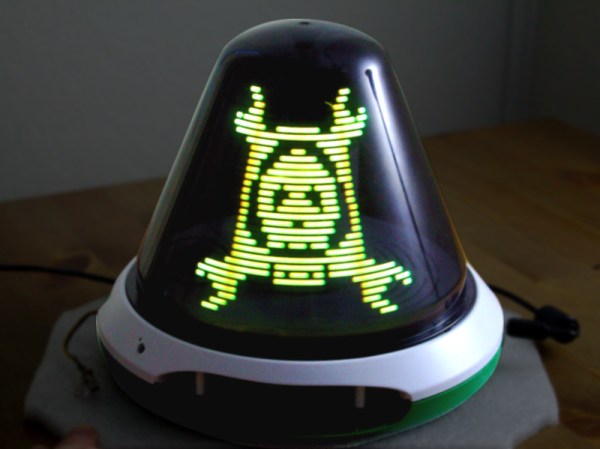
[Harry] wrote in with his hack of the Crayola Light Designer. The Light Designer is a pretty unique toy that lets kids write on a cone-shaped POV display with an infrared light pen. [Harry] cracked one open and discovered it has a spinning assembly with a strip of 32 RGB LEDs for the display and a strip of photodiodes to detect pen position. These were ripe for the hacking.

The spinning assembly uses several slip ring connections to send power and data to the spinning assembly. [Harry] connected a logic analyzer to several of the connections to determine which lines were clock, data, and frame select (the strip is split into 2 16-led “frames”). He went on to reverse-engineer the serial protocol so he could drive the strips himself.

Instead of reverse-engineering the microcontroller on the product’s PCB, [Harry] decided to use a Leostick (Arduino Leonardo clone) to control the LEDs and spinner. He mounted the Leostick on the shaft of the spinning assembly, and powered it over the slip ring connections. After adding some capacitance to make up for noisy power from the slip rings, [Harry] had the POV display up and running with his own controller. Check out the video after the break to see the hacked POV display in action.

Continue reading “Hacking The Crayola Digital Light Designer”

Reverse Engineering A Huge LED Display

muchosLEDs
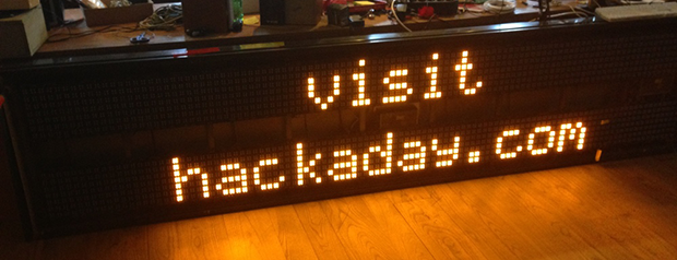
In a fit of awesome salvaging, [Piet] picked up a huge, 16 character, 2 line display. It’s monstrous, designed for outdoor installations; road signs, train stations, and the like. It also draws 23 Watts when nothing is being displayedmaking this the perfect piece of salvaged equipment to reverse engineer.

The display was originally connected to a computer running proprietary software. The protocol between the display and computer is also proprietary, giving [Piet] the choice of either reverse engineering the protocol, or reverse engineering the hardware and building a new driver board. For anyone with a soldering iron, the second option is the simplest.

Disassembling the display, [Piet] found each character in the display was its own board with a 7×14 array of pixels, each with four LEDs. The rows and columns of each character are addressed with a shift register, and with an Arduino, [Peit] got a single character working.

The Arduino would struggle to display all the characters in the display, so a Raspi was pulled out, a driver and frame generator written, and the whole thing connected to Twitter It’s a beautifully display that draws 200 Watts when its scanning the pixels, and a wonderful reuse of disused hardware. Video below.

Continue reading “Reverse Engineering A Huge LED Display”

Aluminum LED Matrix Looks Professionally Made

IMG_1073

[David Donley] has wanted to make a LED matrix for a while now, and has decided to finally pull the trigger — after all, that many LEDs certainly aren’t cheap!

He’s using a set of 16 Adafruit 8×8 NeoPixel LED Matrices (almost $600 worth of LEDs) and a BeagleBone Black to control them. To mount the LED matrices he bought a sheet of 6061-T6 aluminum for two purposes — one to act as a giant heatsink, and two, to look cool. All he had to do was drill some holes in the sheet for the connectors, and then use 3M 300LSE double-sided adhesive to stick the NeoPixels to the surface. The result is a border-less display that looks clean and professional.

To power the array he’s using a 5V 90A power supply — at full brightness these LEDs can consume around 325W, or 65A at 5V!  Taking notes from the opensource LEDscape code on GitHub he’s made his own software to control the display — stick around after the break to see it in action.

Continue reading “Aluminum LED Matrix Looks Professionally Made”

Blinkenschild, The RGB LED Display For Every Occasion

turd

One morning [overflo] decided to protest the European Parliament’s stance on equine rights of defecation, a cherished liberty dating back to the time of Charlemagne. The best way to do this is, of course, blinking lights. He calls his project Blinkenschild, and it’s one of the best portable LED displays we’ve seen.

The display is based around fifteen RGB-123 LED panels, each containing an 8×8 matrix of WS2811 LEDs. That’s 960 pixels, all controlled with a Teensy 3.1. Power is supplied by fifteen LiPo cells wired together in parallel giving him 6 Ah of battery life. Clunky, yes, but it’s small enough to fit in a backpack and that’s what [overflo] had sitting around anyway.

The animations for the display are generated by Glediator, an unfortunately not open source control app for LED matrices. Glediator sends data out over a serial port but not over IP or directly into a file. Not wanting to carry a laptop around with him, [overflo] created a virtual serial port and dumped the output of Glediator into a file so it could be played back stored on an SD card and controlled with an Android app. Very clever, and just the thing to raise awareness of horse and Internet concerns.

Video below.

UPDATE: Check out [overflo’s] clarification in the comments below.

Continue reading “Blinkenschild, The RGB LED Display For Every Occasion”

An Even Larger Array Of Many LEDs And No Ping-Pong balls

Color Led Matrix

[George] has gone pro with his latest RGB LED panel. We’ve chronicled [George’s] journey toward the elusive land of LED nirvana for a couple of years now. He started with an 8×8 rainbow board of many ping-pong balls. When that wasn’t enough, he upped the ante to a 32×16 array of ping-pong balls. Still not satisfied, [George] has now increased the size to two 20×15 panels, for a total of 600 LEDs. While this is only a modest size increase from the previous incarnation, the major changes here have been in the design and construction of the array.

[George] found himself using his LED panels in some professional settings. The stresses of moving and rigging the panels revealed several design weaknesses. The point to point discrete LED design tended to short, leading to troubleshooting by poking at wires in a dark club. The control code was also a mixed bag of solderlab’s code, [George’s] code, and various scripts. Even the trademark ping-pong ball light diffusers were a problem, as they created a fire hazard. [George] took all the lessons from the first and second LED arrays and started a new design – the MX3. The panel frames were constructed by a professional metal shop. Starting with a square steel tube backbone, and aluminum panel shell was welded into place. The steel tube provides a hardpoint mount for any number of rigging options. The front panels are medium-density fibreboard, treated with a fire-retardant paint.

The electronics have also changed. Gone are the individual RGB LEDs. [George] has switched over to the common WS2812 LED strings. Panel mounted Raspberry Pis control the LED strings. Communication is via Art-Net, an Ethernet implementation of the common DMX512 protocol commonly used in stage lighting. The final result looks great.  We’re impressed with how much [George] has accomplished at such a young age (He was 16 last June).

Continue reading “An Even Larger Array Of Many LEDs And No Ping-Pong balls”

Raspberry Pi Driven 128×32 LED Sign

Looks like a commercial LED display sign… right? Not even close. This is a project of [Jon’s] from over a year ago, and it is a very impressive 128×32 LED display board, driven using a single Raspberry Pi.

It’s made of eight “P10” 32×16 LED panels that he bought off of eBay, housed in a wooden frame he built himself. The display runs off of a single Raspberry Pi and can receive a video signal from anything with an Ethernet port. The individual boards are daisy-chained in a rather odd arrangement to minimize cable length, which [Jon] says helps with clocking the data fast — he’s able to parse 2 bits per pixel to refresh the display at an impressive 400+ frames per second.

To power the display, he’s using a single ATX power supply with the Pi connected to the standby 5V power line. This is to avoid a voltage drop which might cause the Pi to crash — when all LEDs are on the display can draw a healthy 32A of juice. The P10’s use shift registers to serially load the pixel data. At any time, the 4096 pixel display can have 1024 pixels on, which means a fairly fast clock is required to update the display.

[Jon] has shared all the source code on his blog, and has a fairly in-depth explanation of all the systems used. Check it out for yourself, and don’t forget to stick around after the break to see the display in action!

Continue reading “Raspberry Pi Driven 128×32 LED Sign”