Regular Hackaday readers are surely familiar with Nixie tubes: the fantastically retro cold cathode display devices that hackers have worked into all manner of devices (especially timepieces) to give them an infusion of glowing faux nostalgia. But unfortunately, Nixie displays are fairly fragile and can be tricky to drive due to their high voltage requirements. For those who might want to work with something more forgiving, a possible alternative is the Numitron that uses incandescent filaments for each segment.
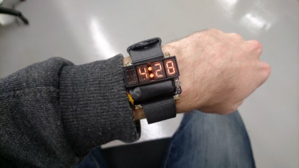
 There hasn’t been a lot of prior-art that utilizes Numitrons, but that might be changing, given how fantastic this wristwatch created by [Dycus] looks. With a multi-day battery life, daylight readability, and relatively straightforward construction, the Filawatch is likely to end up being something of a reference design for future Numitron watches.
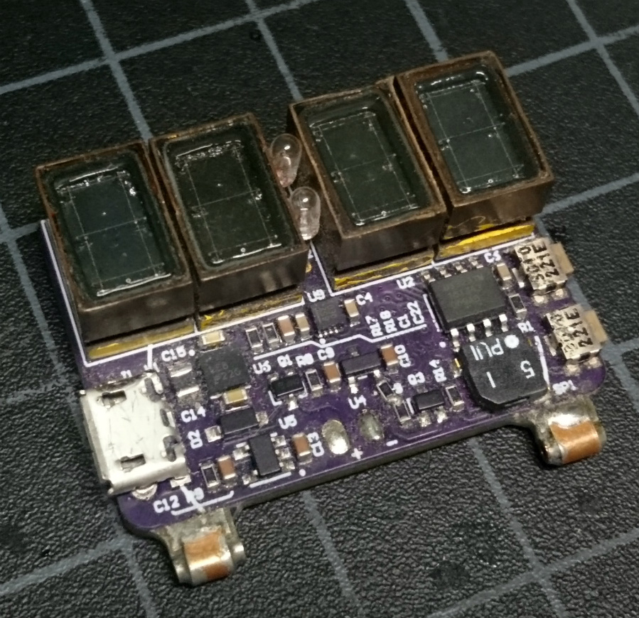
[Dycus] has gone through three revisions of the Filawatch so far, with probably at least one more on the way. The current version is powered by a ATmega328 microcontroller with dual 16-bit LED drivers to control the filaments in the KW-104S Numitron display modules. He’s also included an accelerometer to determine when the wearer is looking at the display, and even a light sensor to control the brightness of the display depending on the ambient light level.
If there’s a downside to Numitron displays, it’s their monstrous energy consumption. Just like in the incandescent light bulbs most of us have been ditching for LED, it takes a lot of juice to get that filament glowing. [Dycus] reports the display draws as much as 350 mA while on, but by lighting it up for only five seconds at a time it can be checked around 150 times before the watch needs to be recharged.
Its been a few years since we’ve seen a Numitron watch, and it’s interesting to see how the state of the art has advanced.
[via /r/electronics]