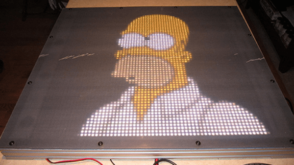
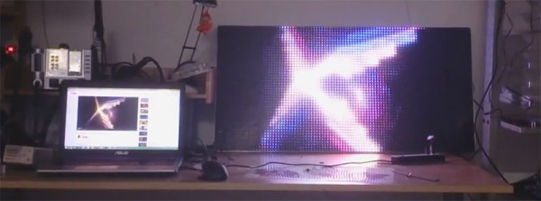
A few links posts ago, we wrote something about a company selling huge LED panels on eBay, ten panels for $50. Those panels are gone now, but a few lucky hackers got their hands on some cool hardware. Now there’s a project to reverse engineer these Barco NX-4 LED panels. Who’s going to be the first to figure out how to drive these things? Doesn’t matter — it’s a group project and we’re all made richer by the contributions of others.
Prague is getting a new hackerspace.
A year and a half ago, a $79 3D printer popped up on Kickstarter. I said I would eat a hat if it shipped by next year. Seeing as how it’s basically November, and they’re not selling a $79 printer anymore — it’s $99 — this might go down as one of my rare defeats, with an asterisk, of course. I’m going to go source some very large fruit roll-ups and do this at Supercon. Thanks, [Larry].
Speaking of bets, this week Amazon introduced the most idiotic thing ever invented. It’s called Amazon Key. It’s an electronic lock (dumb), connected to the Internet (dumber), so you let strangers into your house to deliver packages (dumbest). CCC is in a few months, so I don’t know if Amazon Key will be hacked by then, but I’m pretty confident this will be broken by March.
The Lulzbot Taz is one of the best printers on the market, and it is exceptionally Open Source. The Taz is also a great printer for low-volume production. It was only a matter of time until someone built this. The Twoolhead is a parallel extruder for the Taz 6. Instead of one extruder and nozzle, it’s two, and instead of printing one object at a time, it prints two. Of course it limits the build volume of the printer, but if you need smaller parts faster, this is the way to go.
Hey, did you hear? Hackaday is having a conference the weekend after next. This year, we’re opening up the doors a day early and having a party at the Evil Overlord’s offices. Tickets are free for Supercon attendees, so register here.
At CES this year, we caught wind of one of the coolest advances in backyard astronomy in decades. The eVscope is ‘astrophotography in the eyepiece’, and it’s basically a CCD, a ton of magic image processing, and a small display, all mounted inside a telescope. Point the scope at a nebula, and instead of seeing a blurry smudge, you’ll see tendrils and filaments of interstellar gas in almost real-time. Now the eVscope is on Kickstarter. It’s a 4.5 inch almost-Newtonian (the eyepiece is decoupled from the light path, so I don’t even know how telescope nomenclature works in this case), an OLED display, and a 10-hour battery life.
Is the fidget spinner fad over? Oh, we hope not. A technology is only perfected after it has been made obsolete. Case in point? We can play phonographs with lasers. The internal combustion engine will be obsolete in automobiles in twenty years, but track times will continue going down for forty. Fidget spinners may be dead, but now you can program them with JavaScript. What a time to be alive!
Audio tomphoolery even an idiot tech blogger can see through! I received a press kit for a USB DAC this week that included the line, “…low drop out voltage regulators running at 3.3 V, meaning the 5 V USB limit is well preserved.” Yes, because you’re running your system at 3.3 V, you won’t draw too much current from a USB port. That’s how it works, right?
[Peter Sripol] is building an ultralight in his basement. The last few weeks of his YouTube channel have been the must-watch videos of the season. He’s glassed the wings, installed all the hardware (correctly), and now he has the motors and props mounted. This is an electric ultralight, so he’s using a pair of ‘150 cc’ motors from HobbyKing. No, that’s not displacement, it’s just a replacement for a 150 cc gas engine. On a few YouTube Live streams, [Peter] did what was effectively a high-speed taxi test that got out of hand. It flew. Doing that at night was probably not the best idea, but we’re looking forward to the videos of the flight tests.