[Dan] is an element collector, someone who gets his socks knocked off by bismuth crystals and the orange vapor of bromine. Of course every element collector needs a proper display case, and since the periodic table table idea is cliché, [Dan] decided to build an elemental display that’s also a really awesome LED wall.
The build started off as most do with a few sheets of plywood and 120 acrylic shelves for each item in [Dan]’s collection. The real magic happened when [Dan]’s buddy [Bill] was called in to make the display a little more interesting.
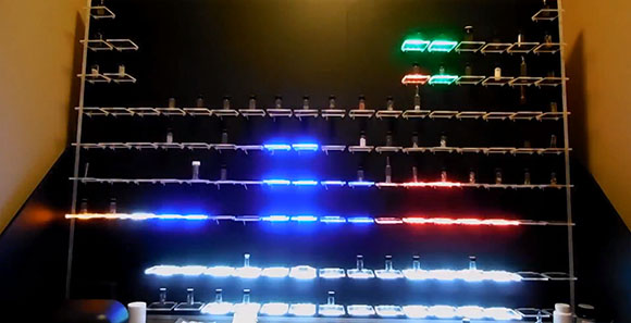
Behind each acrylic shelf is a three-LED section of a LED strip, each part of the periodic table having a different color. The 120 individual shelving units are broken down into 16-shelf groups, each driven by a custom LED driver board. These driver boards are connected to a master Arduino with phone cables and make wonderful use of a very neat TCL5940 Arduino library.
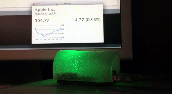
The elemental display has a few options; all-on, twinkling, an Apple ‘breathing’ mode, and a graphic eq, as shown in the video after the break.