X-Ray Vision For FPGAs: Using Verifla

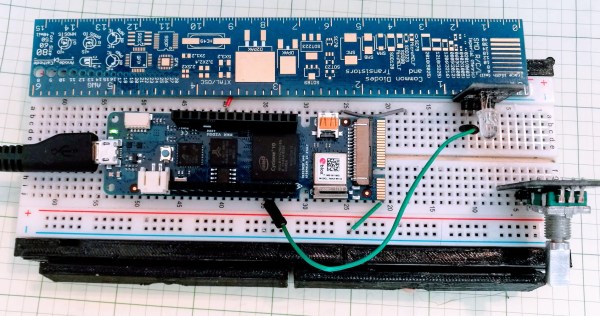
Last time I talked about how I took the open source Verifla logic analyzer and modified it to have some extra features. As promised, this time I want to show it in action, so you can incorporate it into your own designs. The original code didn’t actually capture your data. Instead, it created a Verilog simulation that would produce identical outputs to your FPGA. If you were trying to do some black box simulation, that probably makes sense. I just wanted to view data, so I created a simple C program that generates a VCD file you can read with common tools like gtkwave. It is all on GitHub along with the original files, even though some of those are not updated to match the new code (notably, the PDF document and the examples).

If you have enough pins, of course, you can use an external logic analyzer. If you have enough free space on the FPGA, you could put something like SUMP or SUMP2 in your design which would be very flexible. However, since these analyzers are made to be configurable from the host computer, they probably have a lot of circuitry that will compete with yours for FPGA space. You configure Verifla at compile time which is not as convenient but lets it have a smaller footprint.

Continue reading “X-Ray Vision For FPGAs: Using Verifla”

Flash: Arduino Vidor FPGA Instructions Hit France

If you speak French and you have an Arduino Vidor 4000, you are in luck because there’s some good news. The good news is there’s finally some inside information about how to configure the onboard FPGA yourself. The bad news though is that it is pretty sparse. If your high school French isn’t up to the task, there’s always Google Translate.

We knew some of this already. You’ll need Quartus, the FPGA design tool from Altera — er, Intel — and we know about the sample project on GitHub, too. Instead of using conventional Verilog or VHDL, the new information uses schematic capture, but that’s OK. All the design entry winds up in the same place, so it should be easy to adapt to the language of your choice. In fact, in part 2 they show both some schematics and some Verilog. Google Translate does have a little trouble with code comments, though. If you want something even stouter, there’s an example that uses Verilog to output a video frame.

Continue reading “Flash: Arduino Vidor FPGA Instructions Hit France”

How To Add UART To Your FPGA Projects

Being able to communicate between a host computer and a project is often a key requirement, and for FPGA projects that is easily done by adding a submodule like a UART. A Universal Asynchronous Receiver-Transmitter is the hardware that facilitates communications with a serial port, so you can send commands from a computer and get messages in return.

Last week I wrote about an example POV project that’s a good example for learn. It was both non-trivial and used the board’s features nicely. But it has the message hard coded into the Verilog which means you need to rebuild the FPGA every time you want to change it. Adding a UART will allow us to update that message.

The good news is the demo is open source, so I forked it on GitHub so you can follow along with my new demo. To illustrate how you can add a UART to this project I made this simple plan:

Continue reading “How To Add UART To Your FPGA Projects”

Learn FPGA With This Persistence Of Vision Hack

Everybody wants to give FPGA development a try and here’s a great way to get into it. You can build your own Persistence of Vision display using a $30 dev board. It’s a fun project, and you’ll learn quite a bit about designing for an FPGA, as well as using the Quartus design software.

The inspiration for this article comes from [vpecanins] who did an example project where you wave the board back and forth and a message appears in mid air. This uses the MAX1000, a pretty powerful yet odd FPGA board for about $30. It contains an Intel MAX10 (when did Intel start making FPGAs? Remember, Intel bought Alterra back in 2015). I find the board odd because it also holds an accelerometer that you can talk to using SPI. That’s a little strange for a generic FPGA board, but paired with eight on-board LEDs it’s perfect for this demo.

Since I didn’t find any written documentation for this example, I thought we’d help out and take you on a step-by-step tour of the project. What’s more, in a future installment, I’ll show you how to make some significant changes to the tutorial that will make it even more practical as a base for other projects.

Continue reading “Learn FPGA With This Persistence Of Vision Hack”

Arrow’s $30 FPGA Board Reviewed

We like cheap FPGA boards. It isn’t just that we’re cheap — although that’s probably true, too — but cheap boards are a good way to get people started on FPGAs and we think more people should be using FPGAs more often. One inexpensive board is the Max-1000 from Trenz and Arrow. At $29, it is practically an impulse buy. [ZipCPU] did a great write up on his experience using the board. He found that some of it was good, some was bad, and some was just plain ugly. Still, for $30, it seems like this might be a nice board for some applications or for getting started.

Billed an IoT Maker Board, the tiny board sports a Intel (formerly Altera) MAX10 device with 8,000 logic elements, a USB programming interface onboard, 8 MB of SDRAM, and both PMOD and Arduino MKR headers. The MAX10 has an analog to digital conversion block (with an analog mux for up to nine channels) and the ability to host a 32-bit soft controller onboard, too.

Continue reading “Arrow’s $30 FPGA Board Reviewed”