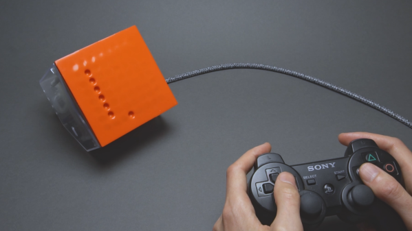
A man’s hands are shown holding a video game controller. A cable runs to a box with an orange front surface, which has a series of divots arranged in a points on a grid. These divots form a vertical line, with one other divot to the right of and below the line.

Playing Snake With A Pneumatic Display

[soiboi soft]’s vacuum-driven dot matrix display is part suction gripper, part touchscreen, and altogether impressive. Its display capabilities are entirely shadow-based, with each pixel being made of a cavity behind a flexible silicone sheet; when the display’s microfluidic logic circuitry activates a pixel, a vacuum pump pulls the sheet inwards, creating a visible hollow.

As in previous iterations, the display’s control circuitry is built around a pneumatic “transistor”, which allows an air channel to be opened or closed by applying vacuum to a control channel. As a first test, [soiboi soft] built a 16-pixel dot matrix display. Eight control channels – four row and four column channels – are multiplexed to individually control each pixel. The transistors act like one-way valves, so the pixels hold their state, even when pressed in by hand; simply add some circuitry to read a pixel’s state, and it would be a fully-functioning touchscreen. The supporting pneumatics also got an upgrade; the solenoid valves now cleanly mount to the back of the board, and the vacuum pump connects via a Luer lock adapter.

The 3D printing used to make certain parts and silicone molds caused issues when scaling up to a 64-pixel display, however. The parts were warping, destroying the seal necessary to keep pixels “on”. To straighten them out, [soiboi soft] pressed the printed part against a flat glass build plate in a vacuum bag and annealed it at 60 Celsius for several hours. This worked quite well, particularly when slightly raised rings were printed around the area to be sealed. Once all these bugs were worked out, the display was clear and decently responsive. [soiboi soft] was able to display letters, numerals, and animations, and even able to play Pong and Snake. It won’t be setting any refresh rate records, but it was nevertheless fully usable.

For another approach to playing Snake with microfluidics, check out this project. If printing molds and casting silicone seems too fiddly, there are always other ways to make microfluidic circuits.

Brain on a chip setup with a hand and a dropper

Gray Matter On A Chip: Building An Artificial Brain With Luminol

Ever wondered if you could build a robot controlled by chemical reactions? [Marb] explores this wild concept in his video, merging chemistry and robotics in a way that feels straight out of sci-fi. From glowing luminol reactions to creating artificial logic gates, [Marb]—a self-proclaimed tinkerer—takes us step-by-step through crafting the building blocks for what might be the simplest form of a chemical brain.

In this video, the possibilities of an artificial chemical brain take centre stage. It starts with chemical reactions, including a fascinating luminol-based clock reaction that acts as a timer. Then, a bionic robot hand makes its debut, complete with a customised interface bridging the chemical and robotic worlds. The highlight? Watching that robotic hand respond to chemical reactions!

The project relies on a “lab-on-a-chip” approach, where microfluidics streamline the processes. Luminol isn’t just for forensic TV shows anymore—it’s the star of this experiment, with resources like this detailed explanation breaking down the chemistry. For further reading, New Scientist has you covered.

We’ve had interesting articles on mapping the human brain before, one on how exactly brains might work, or even the design of a tiny robot brain. Food for thought, or in other words: stirring the gray matter.

Continue reading “Gray Matter On A Chip: Building An Artificial Brain With Luminol”

An Open-Source Microfluidic Pump For Your Science Needs

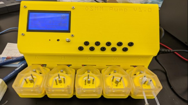
When it comes to research in fields such as chemistry or biology, historically these are things that have taken place in well-financed labs in commercial settings or academic institutions. However, with the wealth of technology available to the average person today, a movement has sprung up of those that run advanced experiments in the comfort of their own home laboratory. For those needing to work with very tiny amounts of liquid, [Josh’s] microfluidics pump may be just the ticket.

Consisting of a series of stepper-motor driven pumps, the hardware is inspired by modern 3D printer designs. The motors used are all common NEMA items, and the whole system is driven by the popular Marlin firmware. The reported performance is impressive, delivering up to 15 mL/min with accuracy to 0.1uL/min. That’s a truly tiny amount of fluid, and the device could prove highly useful to those exploring genetics or biology at home.

The great thing about this build is that it’s open source. [Josh] took the time to ensure that it was easily moddable to work with different tubing and materials, such that others could spin up a copy using whatever was readily available in their area. Performance will naturally vary, but if you’re experienced enough to build a microfluidic pump, you’re experienced enough to calibrate it, too. Design files are on Github for those keen to build their own.

We’ve seen other builds in this area before, too. We look forward to seeing some fun science done with [Josh]’s build, and look forward to seeing more DIY science gear in the future!

Easy DIY Microfluidics

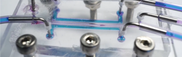
Microfluidics, the precise control and manipulation of small volumes of liquids, is heavily used in any field that does small-scale experiments with expensive reagents (We’re looking at you, natural sciences.) However, the process commonly used to create microfluidic devices is time and experience intensive. But, worry not: the Uppsala iGEM team has created Chipgineering: A manual for manufacturing a microfluidic chip.

Used while developing everything from inkjet print heads to micro-thermal technologies, microfluidic systems are generally useful. Specifically, Uppsala’s microfluidic device performs a simple biological procedure, a heat-shock transformation, as a proof of concept. Moreover, Uppsala uses commonly available materials: ready to pour PDMS (a biologically compatible silicon) and a 3D printed mold. Additionally, while the team used a resin 3D printer, there seems to be little reason that a fused deposition modeling (FDM) printer wouldn’t work just as well. Particularly interesting is how they sandwich their PDMS between two plates, potentially allowing easy removal and replacement of reagents without external mechanisms. And, to put the cherry on top, Uppsala’s well-illustrated documentation is a joy to read.

This isn’t the first time we’ve covered microfluidic devices, and if you’re still in the prototyping phase, these microfluidic LEGO-like blocks might be what you need. But, if you prefer macrofluidics, this waste shark that aims to clean our oceans might be more your style.

Octobot soft body robot

Soft Robot With Microfluidic Logic Circuit

Perhaps our future overlords won’t be made up of electrical circuits after all but will instead be soft-bodied like ourselves. However, their design will have its origins in electrical analogues, as with the Octobot.

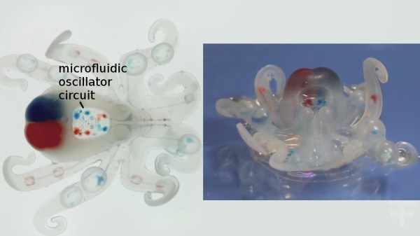
The Octobot is the brainchild a team of Harvard University researchers who recently published an article about it in Nature. Its body is modeled on the octopus and is composed of all soft body parts that were made using a combination of 3D printing, molding and soft lithography. Two sets of arms on either side of the Octobot move, taking turns under the control of a soft oscillator circuit. You can see it in action in the video below.

Continue reading “Soft Robot With Microfluidic Logic Circuit”

Microfluidic Art


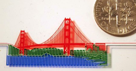
Microfluidics expert [J. Tanner Neville] decided to turn his work into art. Along with his student, [Austin Day], they turned lab chips into miniscule works of art by developing a technique of patterning proteins onto substrates. Each colored line you see is actually a groove full of liquid about 20 microns in width. Another student of [Neville’s], [Albert Mach], is currently working on a method of preserving the liquid for longer amounts of time. As you can probably guess, the dye tends to dry up within a few days. He is also taking submissions for artwork, so we encourage you to submit! We’re certainly looking forward to what else [Neville] and his students come up with next.

[via io9]