oscope-reverse-engineering

Reverse Engineering An Oscilloscope Circumvents Vendor Crippleware

The crew over at the Hungarian Autonomous Center for Knowledge (H.A.C.K.) say they aren’t the most well-funded organization out there, so they were stoked when they found they could afford to bring a slightly used UNI-T UT2025B digital oscilloscope into the shop. As they started to tinker with it, the scope revealed one major shortcoming – screenshots were only accessible via a USB connection to a Windows computer.

Since they didn’t have any Windows boxes in house, [András Veres-Szentkirályi] decided he would try reverse-engineering the protocol so they could get access to this useful feature.

He set up a Windows VM, and using Wireshark on the host Linux box, [András] sniffed the data passing over the scope’s USB interface. He was able to identify what looked like image packets being sent to the VM, which he was able to decode using a small Python script. The resultant images were monochrome and they didn’t look quite right, but it was a start. As he dug further [András] found that he was overlooking some of the color data packed into the images, and after a bit of fiddling he got the sharp, colorful image you see above.

It turns out that while the scope has a monochrome LCD, it sends 16-bit color images over the USB interface – images that the Windows’ client degrades before displaying them on the screen. So in the end, he was not only able to get the scope working on any OS with the ability to run Python, he was able to grab far better images than the manufacturer ever intended – A very nice hack if we do say so.

Be sure to swing by the H.A.C.K. wiki as well as the project’s github repository if you have one of these scopes and are looking to wring some better images out of the hardware.

Make A Simple O-scope With A FTDI Board And A Couple Of ADC’s

[RandomTask] has posted a nice tutorial on how to use a FTDI serial to usb converter, and a couple analog to digital converters to make a simple software oscilloscope. Using a “Universal Serial to USB converter” and one of many FTDI break out boards, he first reprograms the chip using FTDI’s programming software to put the device into a FIFO (first in first out) mode.

From there a pair of ADC0820 8 bit digital to analog converters are wired up, and input is fed to a couple 555’s for testing. It should be noted that there is no input protection, so things like voltages above 5 volts, or negative voltages are a big no-no with this setup. It still could be very handy while working with micro controllers or other digital circuits.

Data is then sent to the computer and displayed using a VB.net program, which has some basic features like scale and triggering, but also contains a couple bonuses like Calc Freq and Calc V delta calculation.

Many people have these little serial to usb converters, and might be in need of a simple scope. If you’re one of them, then you can cobble this together pretty darn quickly, and cheaply.

Oscilloscope Clock Made Possible By Dumpster Diving

We see people driving around the night before trash collection and reclaiming items doomed to the land fill (or on their way to recycling… who knows). We’re beginning to think we need to join those ranks. Case in point is this vintage oscilloscope which [Bob Alexander] plucked from the curb in the nick of time. Here’s the kicker, when he got it home he found it still worked! He couldn’t let this opportunity go to waste, so he figured out how to turn it into a clock without losing the ability to use it as a scope.

You probably already know that it’s possible to display your own graphics on an oscilloscope. In fact, you can buy a board from Sparkfun which will turn the scope into an analog clock, and that’s exactly what [Bob] did. But he was met with two problems, the X-axis was flipped and he didn’t have an easy way to power the board.

He struggled with the voltage supply, frying his first attempt at boosting the internal 6.3V supply to use with a linear 5V regulator. His second attempt worked though, soldering a 12V regulator to the transformer. He was then on to the X-axis correction, using a rail-to-rail op-amp to invert the signal. The project finishes by adding toggle controls and buttons on the back of the case to switch between scope and clock modes, and to set the time.

Homebrew On The Rigol DS1052E ‘scope

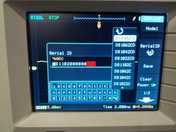
We love our little Rigol 1052E oscilloscope. It’s seen us through some perplexing problems and loved being upgraded from 50 MHz to 100 MHz. We’ve always been pleased with its role dictating waveforms for us, but we never thought we’d see homebrew apps for our little ‘scope.

We’re not exactly sure who [Krater] is, but he’s been working on some homebrew development for the Rigol DS1052E oscilloscope. Right now the capabilities are somewhat limited; all programming is via PEEKs and POKEs. Still, this is a fairly impressive development.

This wonderful little ‘scope has already had some time in the limelight by being easy to upgrade to 100 MHz. Hopefully with the new capabilities (Tetris, somebody make Tetris), this scope will become a staple in workshops around the world.

A tip ‘o the hat goes to [Rainer Wetzel] for sending this one in. Check out the video after the break to see an almost-working game of Pong playing on the 1052E

EDIT: [krater] dropped into the comments to tell us about his blog entry. Keep up the good work.

Continue reading “Homebrew On The Rigol DS1052E ‘scope”

Hackaday Links: December 16, 2011

Free-form Christmas ornament

Here’s [Rob]’s free form circuit that’s a Christmas ornament for geeks. It looks great, but sadly isn’t powered through a Christmas light strand. It’s just as cool as the skeletal Arduino we saw.

Prototyping with flowers

Well this is interesting: protoboard that’s specifically made to make SMD soldering easier. The guys at elecfreaks went through a lot of design iterations to make sure it works.

We’ll call it Buzz Beer

The days are getting longer and cabin fever will soon set in. Why not brew beer in your coffee maker? It’s an oldie but a goodie.

Christmas oscilloscope

With just an ATtiny and a little bit of  futzing around changing the coefficients of a partial differential equation, you too can have your very own oscilloscope Christmas tree. Don’t worry though, there are instructions on how to implement it with an Arduino as well. HaD’s own [Kevin] might be the one to beat, though.

So what exactly does a grip do?

You know what your home movies need? A camera crane, of course. You’ll be able to get some neat panning action going on, and maybe some shots you couldn’t do otherwise. Want a demo? Ok, here’s a guy on a unicycle.

Playing Classic 60s Tunes With An All Electronic Band

house-of-the-rising-sun

If you are considering repurposing some old computer equipment to create music, be aware that the bar has been raised just a tad. YouTube user [BD594] spent some time sifting through his bin of used electronics and put together a 5-piece band that plays a pretty awesome rendition of The Animals’ “House of the Rising Sun”.

Last week, we saw a pretty impressive hack with a floppy drive that could bang out music using a calculator, but this takes things to a whole new level. [BD594] used an old HP ScanJet to simulate the song’s vocals, while an Atari 800XL combined with an oscilloscope is used as an organ. A Ti-99/4a is used in conjunction with another scope to play guitar notes, while a PIC-controlled hard drive does double duty, playing both the bass drum and cymbals.

We dare you to watch the video below and NOT be thoroughly impressed with his work.

[BD594] says that once he has a bit of free time, he’ll be putting out another video – something we’ll be anxiously waiting to see.

Continue reading “Playing Classic 60s Tunes With An All Electronic Band”

Lxardoscope Is A Linux+Arduino Oscilloscope

[Privatier] wrote in to let us know about lxardoscope, his project that lets you use an Arduino as hardware input for a Linux-based oscilloscope display. This implementation offers two channels with about 3000 samples per second from each. He touts some of the GUI options like vertical resolution between 2mV and 10V per division. That part kind of stumps us because we don’t see how a measurement of 10V (or more) can be taken using the schematic included. But you’re comprehension may surpass ours so do take a look yourself.

He is using an Arduino Uno for his testing. But to get around some issues he’s experienced with other USB-based solutions he implemented a serial port connection instead. You’ll need to remove the ATmega chip from the Arduino board after flashing the code to it, and then build a circuit around it which includes a power source where -2.5V is ground and 2.5V is VCC. All in all, you’ll need a 16 Mhz crystal, HEF4069 hex inverter, ATmega8-family microcontroller, and a few passive components to build this on a breadboard.