Learning About Capacitors By Rolling Your Own Electrolytics

Ever wonder what’s inside an electrolytic capacitor? Many of us don’t, having had at least a partial glimpse inside after failure of the cap due to old age or crossed polarity. The rest of us will have to rely on this behind-the-scenes demo to find out what’s inside those little aluminum cans.

Perhaps unsurprisingly, it’s more aluminum, at least for the electrolytics [Denki Otaku] rolled himself at the Nippon Chemi-Con R&D labs. Interestingly, both the anode and cathode start as identical strips of aluminum foil preprocessed with proprietary solutions to remove any oils and existing oxide layers. The strips then undergo electrolytic acid etching to create pits to greatly increase their surface area. The anode strips then get anodized in a solution of ammonium adipate, an organic acid that creates a thin aluminum oxide layer on the strip. It’s this oxide layer that actually acts as the dielectric in electrolytic capacitors, not the paper separator between the anode and cathode strips.

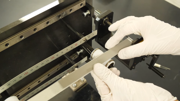
Winding the foils together with the paper separator is pretty straightforward, but there are some neat tricks even at the non-production level demonstrated here. Attachment of lead wires to the foil is through a punch and crimp operation, and winding the paper-foil sandwich is actually quite fussy, at least when done manually. No details are given on the composition of the electrolyte other than it contains a solvent and an organic acid. [Denki] took this as an invitation to bring along his own electrolyte: a bottle of Coke. The little jelly rolls get impregnated with electrolyte under vacuum, put into aluminum cans, crimped closed, and covered with a heat-shrink sleeve. Under test, [Denki]’s hand-rolled caps performed very well. Even the Coke-filled caps more or less hit the spec on capacitance; sadly, their ESR was way out of whack compared to the conventional electrolyte.

There are plenty more details in the video below, although you’ll have to pardon the AI voiceover as it tries to decide how to say words like “anode” and “dielectric”; it’s a small price to pay for such an interesting video. It’s a much-appreciated look at an area of the industry that few of us get to see in detail.

Continue reading “Learning About Capacitors By Rolling Your Own Electrolytics”

Testing Oxide Etchants For The Home Semiconductor Fab

Building circuits on a silicon chip is a bit like a game of Tetris — you have to lay down layer after layer of different materials while lining up holes in the existing layers with blocks of the correct shape on new layers. Of course, Tetris generally doesn’t require you to use insanely high temperatures and spectacularly toxic chemicals to play. Or maybe it does; we haven’t played the game in a while, so they might have nerfed things.

Luckily, [ProjectsInFlight] doesn’t treat his efforts to build semiconductors at home like a game — in fact, the first half of his video on etching oxide layers on silicon chips is devoted to the dangers of hydrofluoric acid. As it turns out, despite the fact that HF can dissolve your skin, sear your lungs, and stop your heart, as long as you use a dilute solution of the stuff and take proper precautions, you should be pretty safe around it. This makes sense, since HF is present in small amounts in all manner of consumer products, many of which are methodically tested in search of a practical way to remove oxides from silicon, which [ProjectsInFlight] has spent so much effort recently to learn how to deposit. But such is the ironic lot of a chip maker.

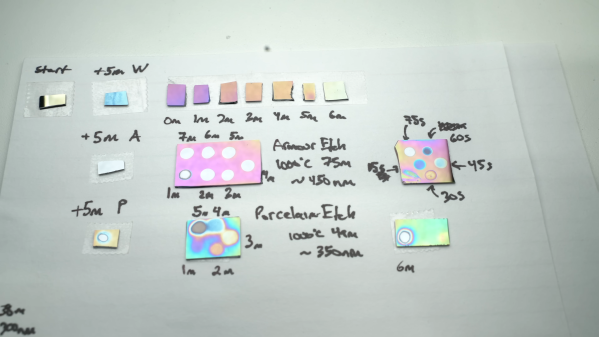
Three products were tested — rust remover, glass etching cream, and a dental porcelain etching gel — against a 300 nm silicon dioxide layer. Etch speed varied widely, from rust remover’s 10 nm/min to glass etching cream’s blazing 240 nm/min — we wonder if that could be moderated by thinning the cream out with a bit of water. Each solution had pros and cons; the liquid rust remover was cheap easy to handle and clean up, while the dental etching gel was extremely easy to deposit but pretty expensive.

The good news was that everything worked, and each performed differently enough that [ProjectsInFlight] now has a range of tools to choose from. We’re looking forward to seeing what’s next — looks like it’ll be masking techniques.

Continue reading “Testing Oxide Etchants For The Home Semiconductor Fab”

How To Solder To Aluminum, Easily

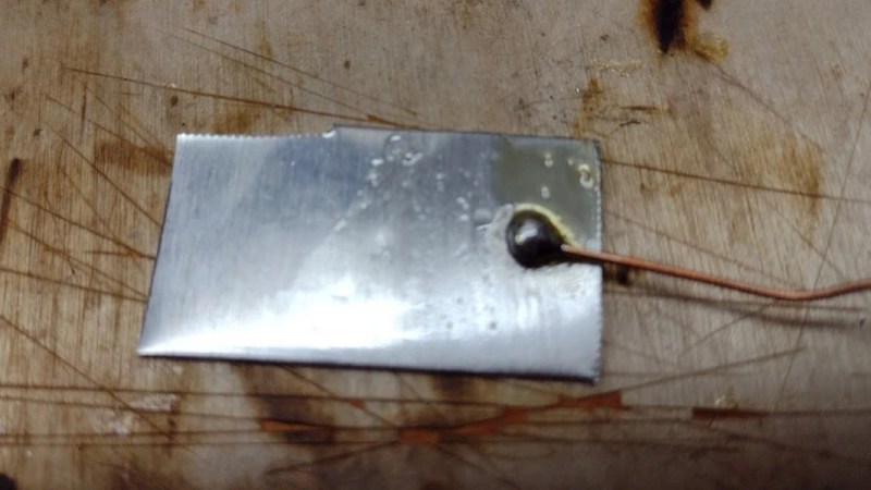
[Ted Yapo] shared a method of easily and conveniently soldering to aluminum, which depends on a little prep work to end up only slightly more complex than soldering to copper. A typical way to make a reliable electrical connection to aluminum is to use a screw and a wire, but [Ted] shows that it can also be done with the help of an abrasive and mineral oil.

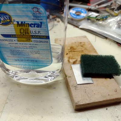
Aluminum doesn’t solder well, and that’s because of the oxide layer that rapidly forms on the surface. [Ted]’s solution is to scour the aluminum with some mineral oil. The goal is to scrape away the oxide layer on the aluminum’s surface, while the mineral oil’s coating action prevents a new oxide layer from immediately re-forming.

After this prep, [Ted] uses a hot soldering iron and a blob of solder, heating it until it sticks. A fair bit of heat is usually needed, because aluminum is a great heat conductor and tends to be lot thicker than a typical copper ground plane. But once the aluminum is successfully tinned, just about anything can be soldered to it in a familiar way.

[Ted] does caution that mineral oil can ignite around 260 °C (500 °F), so a plan should be in place when using this method, just in case the small amount of oil catches fire.

This looks like a simple technique worth remembering, and it seems easier than soldering by chemically depositing copper onto aluminum.