Pi Pico Turns Atari 2600 Into A Lo-fi Photo Frame

The cartridge based game consoles of decades ago had a relatively simple modus operandi — they would run a program stored in a ROM in the cartridge, and on the screen would be the game for the enjoyment of the owner. This made them simple in hardware terms, but for hackers in the 2020s, somewhat inflexible. The Atari 2600 is particularly troublesome in this respect, with its clever use of limited hardware making it not the easiest to program at the best of times. This makes [Nick Bild]’s Atari 2600 photo frame project particularly impressive.

The 2600 has such limited graphics hardware that there’s no handy frame buffer to place image data into, instead there are some clever tricks evolved over years by the community to build up bitmap images using sprites. Only 64 by 84 pixels are possible, but for mid-70s consumer hardware this is quite the achievement.

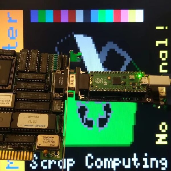
In the case of this cartridge the ROM is replaced by a Raspberry Pi Pico, which does the job of both supplying the small Atari 2600 program to display the images, and feeding the image data in a form pre-processed for the Atari.

The result is very 8-bit in its aesthetic and barely what you might refer to as photos at all, but on the other hand making the Atari do this at all is something of a feat. Everything can be found in a GitHub repository.

If new hardware making an old console perform unexpected tricks is your bag, we definitely have more for you.

Continue reading “Pi Pico Turns Atari 2600 Into A Lo-fi Photo Frame”

The Perfect Pi Pico Portable Computer

[Abe] wanted the perfect portable computer. He has a DevTerm, but it didn’t quite fit his needs. This is Hackaday after all, so he loaded up his favorite CAD software and started designing. The obvious choice here would be a Raspberry Pi. But [Abe] didn’t want to drop in a Linux computer — he was going for something a bit smaller.

An RP2040 Pico would be a perfect fit. Driving a display with the Pico can be eat a lot of resources though. The solution was a PicoVision from Pimoroni. PicoVision uses two RP2040 chips. One drives an HDMI port, while the other is free to run application software. This meant a standard HDMI screen could be used.

The keyboard was a bit harder. After a lot of searching, [Abe] found an IR remote designed for smart TVs. The QWERTY keyboard was the perfect size but didn’t have an interface he could use. He fixed that with an adapter PCB including an I2C GPIO expander chip. A bit of I2C driver software later, and he had a working input keyboard.

Hardware doesn’t do anything without software though. The software running on the handheld is called Slime OS, and the source is available at [Abe’s] GitHub. It’s a launcher, with support for applications written in python. [Abe] has a few basic demos working, but he’s looking for help to get more features up and running.

Although it wasn’t quite what [Abe] was after, our own [Donald Papp] came away fairly impressed when he gave the DevTerm a test drive back in 2022. Something to consider if you’re looking for a Linux handheld and not quite ready to build one yourself.

Continue reading “The Perfect Pi Pico Portable Computer”

JTAG & SWD Debugging On The Pi Pico

[Surya Chilukuri] writes in to share JTAGprobe — a fork of the official Raspberry Pi debugprobe firmware that lets you use the low-cost microcontroller development board for JTAG and SWD debugging just by flashing the provided firmware image.

We’ve seen similar projects in the past, but they’ve required some additional code running on the computer to bridge the gap between the Pico and your debugging software of choice. But [Surya] says this project works out of the box with common tools such as OpenOCD and pyOCD.

As we’ve cautioned previously, remember that the Pi Pico is only a 3.3 V device. JTAG and SWD don’t have set voltages, so in the wild you could run into logic levels from 1.2 V all the way to 5.5 V. While being able to use a bare Pico as a debugger is a neat trick, adding in a level shifter would be a wise precaution.

Looking to get even more use out of those Pi Picos you’ve got in the parts bin? How about using it to sniff USB?

Pi Pico Makes SSTV Reception A Snap

There’s a paradox in amateur radio: after all the time and effort spent getting a license and all the expense of getting some gear together, some new hams suddenly find that they don’t have a lot to talk about when they get in front of the mic. While that can be awkward, it’s not a deal-breaker by any means, especially when this Pi Pico SSTV decoder makes it cheap and easy to get into slow-scan television.

There’s not much to [Jon Dawson]’s SSTV decoder. Audio from a single-sideband receiver goes through a biasing network and into the Pico’s A/D input. The decoder can handle both Martin and Scottie SSTV protocols, with results displayed on a TFT LCD screen. The magic is in the software, of course, and [Jon] provides a good explanation of the algorithms he used, as well as some of the challenges he faced, such as reliably detecting which protocol is being used. He also implemented correction for “slant,” which occurs when the transmitter sample rate drifts relative to the receiver. Fixing that requires measuring the time it took to transmit each line and adjusting the timing of the decoder to match. The results are dramatic, and it clears up one of the main sources of SSTV artifacts.

We think this is a great build, and simple enough that anyone can try it. The best part is that since it’s receive-only, it doesn’t require a license, although [Jon] says he’s working on an encoder and transmitter too. We’re looking forward to that, but in the meantime, you might just be able to use this to capture some space memes.

Continue reading “Pi Pico Makes SSTV Reception A Snap”

Fibonacci Clock Looks Like Beautiful Modern Art

Don’t ask us why, but hackers and makers just love building clocks. Especially in the latter case, many  like to specialize in builds that don’t even look like traditional timepieces, and are difficult to read unless you know the trick behind them. [NerdCave] has brought us a pleasing example of such a thing, in the form of this gorgeous Fibonacci clock.

The build was inspired by an earlier Fibonacci clock that later became a Kickstarter project. Where that build used an Atmega328P, though, [NerdCage] landed on using a Raspberry Pi Pico W instead. The build throws the microcontroller board on a custom PCB, and sticks in inside an attractive 3D-printed enclosure. Black filmanet was used for the body, while white filament was used for the face of each square to act as a diffuser. Addressable RGB LEDs are used to illuminate the five square segments of the clock.

Obviously, you’re wondering how to read the clock. All you need to know is this. The first five numbers in the Fibonacci sequence are 1, 1, 2, 3, and 5. Each square on the clock represents one of these numbers—the side lengths of each square match these numbers. Red and green are used to represent hours and minutes, respectively, while a blue square is representing both. Basically, to get the hour, add up the values of red and blue squares, and to get the minutes, do the same with green and blue squares, but then multiply by 5. In the header image, the clock is displaying 8:55 PM… we think.

We’ve featured Fibonacci-themed clocks before, albeit ones with entirely different visual themes. Video after the break.

Continue reading “Fibonacci Clock Looks Like Beautiful Modern Art”

Pico Logic Analyzer Gets New Version

[Happy Little Diodes] built a Pi Pico logic analyzer designed by [El Dr. Gusman] using the original design. But he recently had a chance to test the newest version of the design, which is a big upgrade. You can see his take on the new design in the video below.

The original design could sample 24 channels at 100 MHz and required two different PCBs. The new version uses a single board and can operate up to 400 MHz. There’s also a provision for chaining multiple boards together to get more channels. You can set the level shifters to use 5 V, 3.3 V, or an external voltage. Since [Happy] is working on a ZX Spectrum, the 5 V conversion is a necessity.

The code is on GitHub, although it warns you that version six — the one seen in the video — isn’t stable, so you might have to wait to make one on your own. The software looks impressive and there may be some effort to integrate with Sigrok.

If you missed our coverage of the earlier version, you can still catch up. Dead set on Sigrok support? [Pico-Coder] can help you out.

Continue reading “Pico Logic Analyzer Gets New Version”

Teaching A Pi Pico E-Ink Panel New Tricks

We’ve noticed that adding electronic paper displays to projects is getting easier. [NerdCave] picked up a 4.2-inch E-ink panel but found its documentation a bit lacking when it came to using the display under MicroPython. Eventually he worked it out, and was kind enough to share with the rest of the class.

These paper-like displays draw little power and can hold static images. There were examples from the vendor of how to draw some simple objects and text, but [NerdCave] wanted to do graphics. There was C code to do it, but it wasn’t clear how to port it to Python.

The key was to use the image2cpp website (we’ve used it before, but you can also use GIMP). Instead of C code, though, you get the raw bytes out and place them in your Python code. Once you know the workflow, it isn’t that hard, and this is an inexpensive way to add a different kind of display to your projects. The same image conversion will help you work with other displays, too.

We aren’t sure what driver chip this particular display uses, but if you have one with the UC8151/IL0373, you can find some amazing MicroPython drivers for those chips.

Continue reading “Teaching A Pi Pico E-Ink Panel New Tricks”