There are times in a tinkerer’s existence where it is convenient to have the ability to plug in and power a lot of USB devices. Sure, you could use a USB hub but this may not be satisfactory if your devices require a lot of current. A computer may work but is not really a stand alone solution.
[Jeff] and the crew over at Make Lehigh Valley ran into this predicament. They were putting on an Adafruit Trinket class and needed a USB power supply to power all of the Trinkets that were going to be used. As any makerspace would do, they built their own USB Power Station, and the final product is certainly overkill for what they needed (that’s not a bad thing).
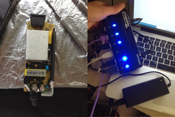
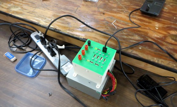
An old ATX computer power supply is a logical component to use for this type of project. These power supplies are usually available in abundance and will provide all the amperage any reasonable amount of 5v USB devices can ask for. The 5v output from the ATX power supply was wired to 8 USB jacks. Keeping up with the project’s resourcefulness, those USB jacks were scavenged from a couple of old PCI-slot USB hub panels. Not satisfied with only USB outputs, the guys also wired up some banana jacks so that 3.3, 5 and 12 volts were available for whatever project was being worked on. A 3D printed enclosure keeps everything neat and tidy.
This project used a bunch of recycled parts and solved a problem faced by the group. If you’re interested in using an ATX power supply to make a more bench-top style power supply then check out this build.