Multi-Function Bench Power Supply

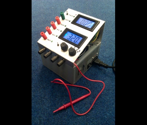
Concerned with your project’s power consumption but don’t want to constantly leave an ammeter wired in series with your power supply? [Rajendra] feels your pain and has recently documented his solution to the problem: a variable-output bench top power supply that clearly displays load current consumption among other things!

Everything is wired up in a nice roomy enclosure that has front-panel access to ±5V and variable outputs, an adjustment potentiometer, and even an input for an integrated frequency counter. A PIC16F689 MCU runs the show and displays the variable output voltage and current on a 16×2 character LCD. Although clearly useful as is, the PIC has plenty of I/Os and muscle left for future expansion and a capacitance meter has already been hinted at as and addition for version 2!

Continue reading “Multi-Function Bench Power Supply”

PC Casemod-inspired Benchtop PSU

benchtop_psu

[Will] had a cheap power supply sitting around, and decided to turn it into a full-featured benchtop PSU. Inspired by some of the other benchtop supplies we have featured in the past, he decided that he wanted his PSU to be more than just a simple-looking box sitting on his work bench. Taking some cues from PC case modding, he put together a unit that is not only very useful, but also quite sharp looking.

The frame of the case was crafted from aluminum angle, while all of the other flat surfaces were made using black polycarbonate. He installed the standard 12v, 3.3v, and 5v terminals you would expect from any benchtop PSU, complete with an LCD display showing the voltages provided by each rail as measured by an Arduino stationed inside the case. Additionally, he installed a variable terminal capable of providing 1.3v-30v, along with its own LCD display. The most unique feature is the multimeter embedded in the front of the case, which makes it virtually impossible to lose.

The case is finished off as you might expect, if you have seen any of his previous work. It features LED lighting on the inside, large fans on either side of the case for optimal air flow, and a pair of machined aluminum handles.

Be sure to check out the quick video below of the PSU being powered on.

Continue reading “PC Casemod-inspired Benchtop PSU”

ATX Psu Turned Into An Adjustable Voltage Bench Supply

Here’s a fancy way to convert an ATX powers supply into a bench supply. [TG] didn’t just cut off the motherboard connector and add banana plugs, but improved the functionality. Right off the bat you’ll notice that he’s added a control panel. There is an Ammeter and Ohmmeter to let you know what the unit is putting out. He added an MIC29152WT adjustable voltage regulator so that he’s not limited to the fixed voltages of the psu. As a final touch he added an external voltage probe which can be used with the flick of a switch. It’s no replacement for a proper bench supply, especially since it doesn’t have adjustable current limiting, but it’s a nice improvement upon previous psu hacks.

Bench Supply With Current Limiting

This is a bench power supply with adjustable voltage and current limiting. [Sylvain’s] creation can regulate 0-25 volts while sourcing 0-5 amps. Current limiting is a nice feature as it will allow you to test your prototypes to ensure the power regulator you choose will not be over or underpowered.

This supply is really a two-in-one. The case has two separate circuits so that you can have different power rails going at the same time. There is a microcontroller involved, but the ATmega32 doesn’t do anything more than measure the voltage and amperage and drive the graphic LCD screen. Two potentiometers are responsible for setting the voltage and limiting the current.

[Thanks Sargonout]

EL Wire: Make It, Connect It, Power It

[Jeri’s] back with a series of videos that outlines the step-by-step electroluminescent wire manufacturing, making EL panels from PCBs, and assembling power supplies for EL hardware. These concepts are actually quite approachable, something we don’t expect from someone who makes their own integrated circuits at home.

The concept here is that an alternating current traveling through phosphors will excite them and produce light. You need two conductors separated by a dielectric to get the job done. For wire, [Jeri] uses one strand of enameled magnet wire and one strand of bare wire. The enamel insulates them, protecting against a short circuit.

But that’s not all, she also tests using a circuit board as an EL panel. By repurposing the ground plane as one of the conductors, and using the solder mask as the dielectric she is able to paint on a phosphor product resulting in the glowing panel.

Finally, you’ve got to get juice to the circuit and that’s where her power supply video comes into the picture. We’ve embedded all three after the break. It’s possible that this is cooler than blinking LEDs and it’s fairly inexpensive to get started. The circuitry is forgiving, as long as you don’t zap yourself with that alternating current.

Continue reading “EL Wire: Make It, Connect It, Power It”

Making Mobile Audio Work At Home

[Nikita] made a great find while cleaning out his garage: a set of audio amplifiers from a 1986 Volvo. After a bit of testing, he dislodged a stuck relay and set out to use these amps for a home audio system. He grabbed some left over brackets from his TV mount and used them as rail mounts. On the back he wired standard speaker connectors and RCA connectors to the wiring harness for the amplifiers. The final aspect is powering up the device, for which he used his ATX psu previously modified as a bench supply. 130-Watts of power for the cost of a few connectors.

We surprise to find we haven’t covered this common ATX bench-supply conversion before. What we have seen is an adapter to use one as a bench supply.

‘tiny’ Power Supply Monitor

[Manekinen] built a power supply monitor based around an AVR ATtiny13. Voltage and amperage are displayed on a 16×2 LCD character display (we’re not sure what the third number is… samples per second?). This is no small feat considering that the tiny13 is an 8-pin chip. He makes it happen by using the pins for both LCD control and ADC input. To make this happen the HD44780 compliant display is used in 4-bit mode. Check out the video after the break and hit up the non-translated page if you want to download the source code and PCB artwork. A note of warning, he’s using the RESET pin for I/O which means once you burn the fuses you’ll need a programmer that has High Voltage Serial Programming capabilities if you want to reprogram the chip. Continue reading “‘tiny’ Power Supply Monitor”