Wardriving For Zigbee

Wardriving started out as a search for unprotected WiFi access points before hot spots were prevalent. And so this ZigBee protocol wardriving hardware which [Travis Goodspeed] put together really gives us a sense of nostalgia for that time. Don’t get us wrong, we love our pervasive WiFi access and don’t wish to go back to simpler times. But if the radio signals your looking for are scarce, locating them provides a challenge.

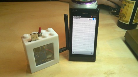
Regular readers will recognize that [Travis] is interested in all things RF. One of his projects included sniffing wireless keyboard packets out of thin air and displaying them on the screen of his Nokia N900. This is right along those lines but he’s upgraded to an N9 phone for the display hardware. He switched up the RF hardware, using a TelosB (a board he’s already familiar with) to get on the 802.15.4 ZigBee spectrum. This dev board has an expansion port which let him use an RN42 module for wireless communications with the phone. This means the sniffing hardware can be hidden away in a backpack or jacket. After all, nobody will question someone walking around staring at a smart phone.

Designing A Smarter RF Transceiver

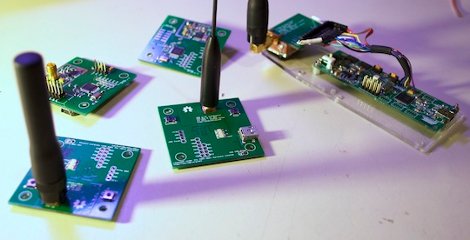
Two  months ago we featured a transceiver based on the Microchip MRF49XA, and a lot of feedback was sent to [hpux735] requesting that some brains be added onto the system. [hpux735] decided that if he was going to do it, might as well go the distance and make a make a native USB transceiver.

The prototype model is designed for use with the Atmel AT90USBKey, and uses the LUFA USB framework. The protocol and packet format was revised, and a Hamming Code implementation was built using look-up tables to give error control. Finally once the prototype was ready to go [hpux735] created some awesome little PCB’s that contain the AVR, radio, antenna hookups, and blinky lights (no project is complete without blinky lights) are all ready to go when you are.

This project has come quite a long way, covers 3 blog pages, uses a fair bit of ribbon cable, but you just got to love when a plan comes together.

Python Maps Mouse Movements On An LED Matrix

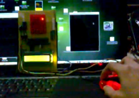
[Vinod Stanur] is working with a mouse input and a microcontroller driven LED matrix. The mouse cursor is tracked inside of a window by Python and the resulting coordinates on the LED grid are illuminated. He calls it an LED matrix “Paint Toy” because one of the features he’s included lets the user create pixel art like in MS Paint.

The 10×8 grid of lights is controlled by a PIC 16F877A. This display orientation is perfect for the 8-bit controller, which uses an array of ten bytes to keep track of the pixel data. A computer running his Python application (which uses the Pygame module to track the mouse movements) communicates with the display board via an RF connection. Five bytes plus a stop character make up the communication packet. The first two bytes contain the coordinates of the cursor, the other three bytes contain mouse button status.

As you can see in the demo after the break, the system is very responsive. The mouse can be moved quickly without latency issues, and if the cursor leaves the tracking window it gets picked up right away when it re-enters.

Continue reading “Python Maps Mouse Movements On An LED Matrix”

Making An RF Controlled Light Switch Work With IR

ir-rf-light-switch

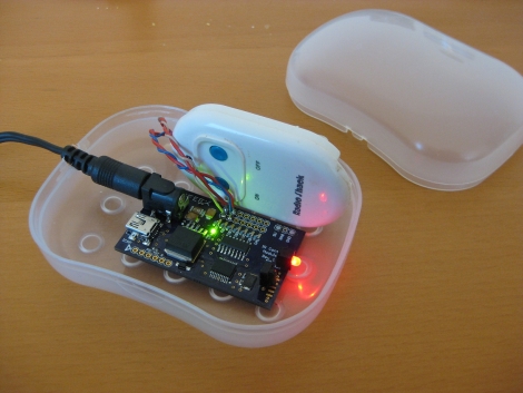
[Gary] had an RF triggered light switch kicking around, and wanted to find a way to control his lights using a home theater remote. The switch, which he bought from RadioShack years ago, came with a simple remote that uses two buttons to toggle the lights on and off. While you might think that switching from RF to IR control would be a step backwards, [Gary] really just wanted to consolidate remotes more than anything else.

He designed a circuit board specifically for interacting with the remote half of his RF controller. It sports a PIC16F628A micro controller, which is tasked with processing IR commands from his home theater remote and triggering the lights when requested.

The code he developed for the project is relatively simple, but very useful all the same. When his board is powered on, it stores the first IR code it receives, then retains it as long as it stays powered on. This lets [Gary] use any button on his remote to turn the lights on and off, without any IR codes permanently defined in software.

As you can see in the video below, the modified switch works just as intended, saving [Gary] from having to walk all the way to the light switch when it’s time to fire up a movie.

Continue reading “Making An RF Controlled Light Switch Work With IR”

Snooping Around In The Iclicker Hardware And Firmware

[Arko] was compelled to purchase an iclicker to use in some of his college courses. It’s similar in size to a television remote control except it only has six buttons and it communicates via radio frequency instead of infrared light. The idea is that classrooms have a base station that the instructor uses, and he or she can ask questions of the class and have instant feedback. Results are often projected on a screen for all to see but only the instructor can get at the breakdown of who answered in what way. In [Arko’s] case, the class awards participation points that you can only get by using this device. He decided to actually learn something from the expenditure by reverse engineering the device.

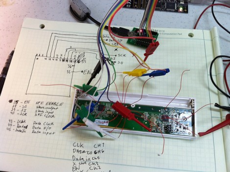
Preliminary hardware inspection told him that it uses an ATmega8 microcontroller and there’s a standard 6-pin ISP footprint just waiting to be populated with a surface mount pin header. Once he soldered on that header, he tried to read out the firmware but the iClicker reset itself. He guessed that there was something going on with the power and ground lines so he soldered directly to them and was able to dump the data–the security fuses are not set. He goes on to snoop in the EEPROM to find where the device ID is stored, and then to watch some of the SPI communications to see what the microcontroller is sending to the radio chip. But there’s a lot left to discover and he’s planning at least two follow-up post to share what he finds.

Just looking to repair your dead device? Check out this tip on battery problems with the iclicker.

2011 CCC R0ket Badge

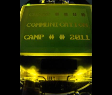
[Geekabit] wrote in asking if we’d seen the 2011 CCC badges yet. The answer is NO, we haven’t seen them because the image above is the only sneek peek we can find on their broken-certificate website. But we are glad that he shared the link with us, because it does tell the tale of what hardware and firmware features will be on this year’s badge.

Right off the bat we need to applaud them for several things. Most notably, the 3.7 volt 600 mAh LiPo battery which can be recharged via the USB port. It boasts an ARM Cortex M3 processor which is running what they call and ‘unbrickable’ bootloader that is programmed via the USB port. You can see there is an LCD screen which we’d guess is about 128×128 pixels (correct us if you know otherwise). You’ll be able to interact using a 5-way button, via the RF transceiver, and possibly using an optical interface but we’re not sure that feature made it into the final design. They’ve also rolled in a shield system for extra harware so that you can design your own add-ons before you get there.

As always, if you get your hands on one of these, we want to hear all about your project as well as get an overview of the stock badge and its features so don’t forget to drop us a line.

Update: [Never_gonna] left a comment with a link to a series of posts about r0cket development including a video which we’ve embedded after the break. Thanks!

Continue reading “2011 CCC R0ket Badge”

Crafting A Hexapod With An RC Controller

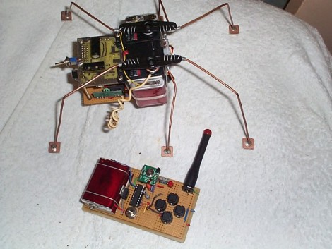
Here’s a fantastic project that lets to drive a hexapod around the room using an RC controller. [YT2095] built the bot after replacing the servo motors on his robot arm during an upgrade. The three cheapies he had left over were just begging for a new project, and he says he got the first proof-of-concept module put together in about an hour. Of course what you see above has gone through much improvement since then.

The three motors are epoxied together, with the one in the middle mounted perpendicular to the motors on either side of it. Those two are responsible for the front and rear leg on each side, with the third motor actuating the two middle legs. It’s a design we’re already familiar with having seen the smaller Pololu version. You might want to check that one out as there’s some slow motion video that shows how this works.

[YT2095] added control circuitry that includes an RF receiver. This lets him drive the little bot around using a transmitter with four momentary push switches on it. We love the idea of using copper clad for the foot pads.