SNES Emulator Has It’s Slot Sealed Shut

If you look closely you’ll notice there’s nowhere to put the game cartridge on this Super Nintendo system. That’s because this is a Rasberry Pi based SNES emulator that plays ROMs, not cartridges. Since the RPi board is used the only limit to what you can play is the board’s RAM and which ROMs you have on the SD card.

The case has basically been gutted and the unused cartridge slot was sealed with some Bondo before painting. In addition to the Rasberry Pi you’ll find a 7-port powered USB hub and a Teensy microcontroller board. The hub allows for the controllers to be connected via USB. The Teensy is recognized as a USB HID device and is used to connect the reset button to a functions on the emulator program. The power switch still works too. To make this happen [MIDItheKID] spliced a USB connector and a microB USB connector to the power switch. We think this draws power from the hub but we’re not 100% sure.

[MIDItheKID] mentions in the Reddit comments that he’s thinking of grabbing that new RPi that has more memory and doing some similar work on his dead PSX.


APRS IGate Built Using A Raspberry Pi

The hardware seen above is used to bridge a local RF radio network to the APRS-IS network. The APRS-IS is an Internet Service that uses a web connection to communicate between APRS networks in different parts of the world. The Raspberry Pi is perfect for this application because of its ability to connect to a network, and its native use of Linux.

On the software side the majority of the work is done by a Python script. It is responsible for setting up and monitoring a connection with an APRS-IS server. To connect to the handheld radio unit a USB sound card was used. The Multimon package is used to send and receive audio packets through this hardware.

[Sunny] has a few upgrades planned for the system. The device needs to report its location to the APRS-IS server and the plan is to add functionality that will look of the WiFi AP’s location automatically. It may also be possible to get rid of the radio all together and use a DVB dongle as a software defined radio.

Raspberry Pi Foundation Looks At Counterfeit Apple Power Supplies

The Raspberry Pi foundation is in a somewhat unique position. They always test the units that get returned to them in hopes that they can improve the design. They often request that the power supply also be sent back with the RPi unit, as we know the board will not work well if the PSU can’t source enough current. And so they’ve been able to get a look at several counterfeit iPhone chargers. This is not one of the recommended ways to power the RPi, but their ability to collect failed hardware means that they have identified three different fakes on the market.

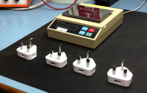
Seen here is a genuine Apple product on the left. The others are fake, with the easiest way of spotting them being the shiny chrome plug connectors. The genuine part has a matte finish on the connectors. There is also a difference in the chamfering, and even a variation on the orientation of the USB port on some of them. Unfortunately we don’t get a look inside, which is what we really wanted. But you can see in the video after the break that weighing the adapter will also give it away as a fake, showing that the components within probably vary quite a bit. This reminds us of some other fake PSUs that have been exposed.

Continue reading “Raspberry Pi Foundation Looks At Counterfeit Apple Power Supplies”

PIC Programming Adapter For The Raspberry Pi

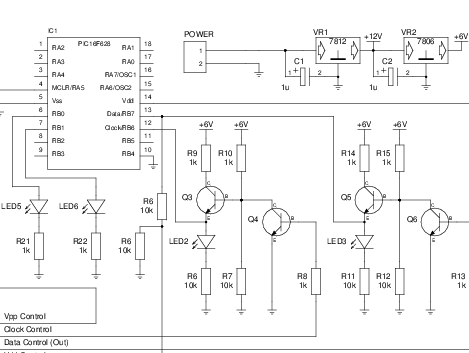
Here’s another offering when it comes to PIC programming from the Raspberry Pi. The design seeks to adapt the GPIO header so that it may be used for programming PIC microcontrollers, but this does involve a bit more than just physically connecting pins to the target chip. Most of the PIC family require a 12V programming level, and this setup makes that possible.

The sets of NPN transistors shown in the schematic fragment above are arranged in darlington pairs. They’re actually switching voltage from the 6V linear regulator built into the system using the Pi’s 3.3V pins. There’s also a 12V regulator, so you’re going to need a power supply that is capable of sourcing more than that.

We’ve seen a similar concept before but this design carries it a step further. There are several status LEDs built into the programmer, and it includes support for detecting which chip is being programmed. So far this covers just four different chips, but we’re sure that it could be adapted to fit your own needs.

[via Reddit]

Malicious Raspberry Pi Power Strip Looks A Bit Scary

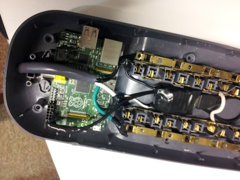
What you see here is a Raspberry Pi shoehorned into a power strip. The idea is to leverage the power and low-cost of this board into a stealthy network observation device. It packs a similar punch as the Power Pwn but should cost at least $1100 less!
The fact that when you plug your Ethernet into this ‘surge protector’ it starts sniffing your traffic doesn’t really scare us. It’s the mains wiring that traverses the RPi itself that’s a bit unnerving. Call us overly-protective, but we like to see some shielding between our high-voltage and low-voltage components. But that aside, the rest of the hack is pretty solid. That item wrapped in electrical tape is a power converter for the board itself. It’s not shown here, but the NIC is patched into the surge protector’s RJ-45 connector. The one thing that might be nice to include is a WiFi nub so that you can access the strip wirelessly. This would open the door for other snooping items, like a small microphone.

BrewPi Is A Raspberry Pi In Charge Of Beer Fermentation

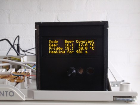
Take a look at BrewPi, a fermentation controller made with a Raspberry Pi. The project hacks control of a refrigerator and a light bulb into the pervue of a Raspberry Pi board. The RPi itself brings network connectivity to the mix. What you end up with is an already highly configurable fermentation system which is perched to receive even more features moving forward.

The man behind the system is [Elco Jacobs]. You may remember his name from the UberFridge project. That was a router-based fermentation controller. This keeps the same great hardware as well as online graphing and control features such as setting plot points for ramping temperature up and down. For now there’s also an Arduino being used which takes care of the hardware switching via json packets received from the RPi. But now that he’s worked out most of the bugs it should be fairly painless to dump the Arduino and build a proper RPi shield for this purpose.

Problems Powering Raspberry Pi From GPIO Header

[Zaion] grabbed an ATX power supply to source the 5V the Raspberry Pi needs to run. The common problem when it comes to RPi supplies is a shortfall in how much current a USB wall adapter can source. The ATX shouldn’t have this problem, but none-the-less he found that the USB ports were only reading about 5V. Strange. He grabbed the soldering iron and fixed the issue with a piece of jumper wire (English translation found in the second half of his post).

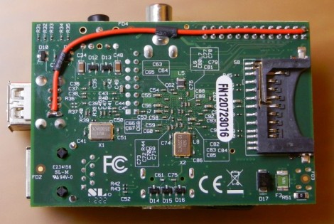
The problem was discovered when trying to get a WiFi dongle to work on one of the RPi’s USB ports. It simply wouldn’t show up, and after going down the blind alley of assuming it was a driver problem he started to investigate the hardware. After discovering the below-nominal voltage [Zaion] measured the resistance between the 5V pin on the GPIO header and the one on the USB port. It reads 3-4 Ohms and he concluded that the trace is too thin. We took a quick look at the schematic for the board and see no reason for the voltage drop. His jumper wire fixed the issue but it leaves us wondering, is this an isolated case, or a design flaw? Tell us what you think in the comments section.