Building Your Own Real Time Clock

diy_rtc

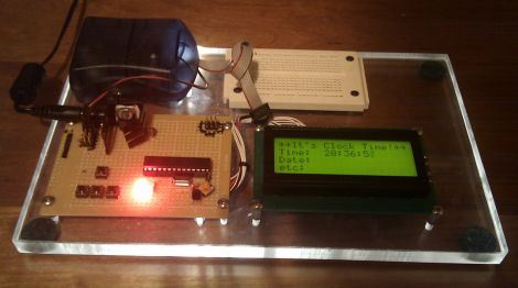
Like many electronics hobbyists, [Pete] found that he had an overwhelming desire to build a clock for himself. He didn’t want to stick a discrete real time clock IC into a box and call it a day, so he opted to construct his own around a microcontroller instead.

After researching the specs on a few RTC ICs, he defined some accuracy requirements for his clock, and got to building. He started out using a 32,768 Hz watch crystal, but found that the accuracy was off by about 46 ppm after only 24 hours of use. That fell well beyond his self-imposed +/- 3 ppm tolerance goal, so he purchased an oscillator with about 500 times the resolution of his previous crystal.

After writing a handful of code to ensure that the clock remains stable, he calculated that his accuracy should be about 0.18 ppm – well within his acceptable tolerance range.

[Pete] says that this is just the first part of his clock construction, and that future revisions should include plenty of additional functionality, so keep an eye out for updates.

15-digit Nixie Clock Contains Mostly Non-useful Information

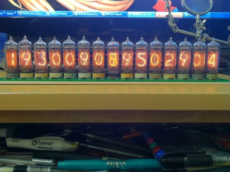
[Jarek Lupinski] is at it again, this time building a clock using 15 Nixie tubes. Just look at the time…. wait, how do you read this now? It’s not seconds since the epoch, but an homage to a very expensive New York City art piece. [Jarek] took his inspiration from the Metronome art installation in Union Square.

We hadn’t heard of it before and were shocked to learn that this art was commissioned at $4.2 million. It belches steam and confuses passersby with its cryptic fifteen digits. It seems that the eight digits on the left mark the current time – two digits for hours, two for minutes, two for seconds, and the final digit for hundreths of a second. The seven remaining digits count down the time left in the day. So when you watch it, you see the significant digits of the display increasing, and the insignificant half decreasing.

The Nixie version rests snuggly on a 15″x4″ PCB. We’re sure it doesn’t number in the millions, but that couldn’t have been cheap to have manufactured. Each tube has its own driver chip, removing the need for multiplexing. An ATmega168 controls the clock (along with some shift registers to expand the I/O count), reading time from a DS1307 RTC chip. It looks fancy, but where’s the belching smoke on this version?

How To Build A Ping-pong Ball Display

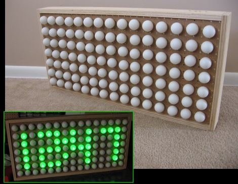
If you’ve been lusting after your own glowing display we’re here to help by sharing some simple building techniques that will result in an interesting project like the one you see above. This is a super-accurate clock That uses ping-pong balls as diffusers for LEDs, but with a little know-how you can turn this into a full marquee display. Join me after break where I’ll share the details of the project and give you everything you need to know to build your own.

Continue reading “How To Build A Ping-pong Ball Display”

Xbee Controlled, Granite-wrapped Clock Travels Into Future

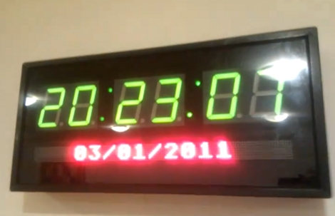
From the looks of it this clock is a couple of months ahead of its time. [Oscar] built the clock (translated) taking time to add a lot of goodies into the mix. First up, the parts you see include six large 7-segment displays for hours, minutes, and seconds as well as an LED marquee which can scroll messages. Inside there’s a temperature and humidity sensor for environmental feedback, and an Xbee module which allows for wireless computer control. Time is kept by a DS1307 real-time clock, which is read by an Arduino Uno, then pushed to the display by the pair of I2C addressable SAA1064 drivers. The whole thing was enclosed in four sheets of granite for the box, and a pane of glass for the front. We sure hope it’s well anchored to that wall. You can see it ticking away after the break.

Continue reading “Xbee Controlled, Granite-wrapped Clock Travels Into Future”

Keep Your Kids In Line With A Time Clock

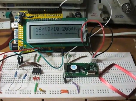
When the cat’s away the mice will play, but a least you’ll know when they came home if you use this time clock. It’s called the Kid-e-log and [John Boxall] developed it to help a friend who wanted to keep track of their teenage children’s after school activities while they were still at work. He figured having them punch a time clock would at least let you know if they came straight home as they were supposed to. An RFID tag was issued to each (no, they didn’t implant the tags) and used to record the time. To keep fraud to a minimum the hardware has a battery back-up for its real-time clock, and the tag read events are stored to EEPROM for retention between power cycles. This doesn’t prevent common tricks like taking the reader with you, or sending your tag with a sibling, but it’s a start. See it in action after the break.

Continue reading “Keep Your Kids In Line With A Time Clock”

Shiny Motorcycle Computer

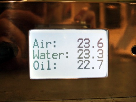
We’re rather surprised at how popular it has become to build your own motorcycle computer. [Mario Mauerer] tipped us off about his shiny motorcycle computer (translated) for his Yamaha XTZ 750. It uses an ATmega644 microcontroller to pull a variety of data together and display it on this white LED backlit display. He connected a flow meter to the fuel line to monitor gas consumption. Oil temperature is captured by inserting a brass tube (containing the sensor) through a hole in the oil cap and soldering it in place. Water temperature is gathered by measuring the external temperature of one of the cooling lines. [Mario] uses a rotary encode with a click function as the control interface device, and a battery backed real time clock keeps time.

A quick look at the PCBs tells the tale of good circuit design. But we do wonder about catching the reflection of the sun in that shiny bezel.

Matrix Clock Is A Breadboarding Win

Normally when we feature a clock made with a 32×8 LED matrix we’d load up an image of the display for the banner photo. But this time around we were so impressed by [JB’s] breadboard work we had to use this image. We see an ATmega168, three buttons, three LEDs, a piezo buzzer, 32.768 kHz crystal, smoothing capacitor, and a few resistors; everything he needed to keep time and display it on the matrix module. If this is just going to sit on your bookshelf for a while it’s a great alternative to point-to-point soldering on a protoboard. Nice work fitting it all on there [JB].