Developed On Hackaday: Setting Up The Project’s Infrastructure

2013-12_Developed_on_Hackaday

We’re pretty sure that most of our readers already know it by now, but we’ll tell you anyway: the Hackaday community (writers and readers) is currently developing an offline password keeper. In the first post of our first DoH series, we introduced the project and called for contributors. In the comments section, we received very interesting feedback as well as many feature suggestions that we detailed in our second write-up. Finally, we organized a poll that allowed everyone to vote on the project’s name.

The results came in: the project’s name will be mooltipass. We originally had thought of ‘multipass’ but [asheets] informed us that Apple and Canon had both applied for this trademark. [Omegacs] then suggested ‘mooltipass’ as an alternative, which we loved even more. A few days ago we set up a google group which is already very active.

An often under-estimated side of a community driven project is its infrastructure and management. (How) can you manage dozens of motivated individuals from all over the globe to work on a common project? How can you keep the community informed of its latest developments?

Continue reading “Developed On Hackaday: Setting Up The Project’s Infrastructure”

Developed On Hackaday: First Feedback From Users

2013-12_Developed_on_Hackaday

Holy cr*p guys… we were amazed by the quantity of positive feedback that was left in the comments section of our last article. We have been featured by Slashdot ! We got plenty of project name suggestions, therefore we organized a poll located at the end of this post to let you decide which one is best. I also received many emails from people eager to start contributing to this offline password keeper project. If you missed the call and want to get involved, it’s still not too late. You can get in touch with me @ mathieu[at]hackaday[dot]com. So far, we have many beta testers, several software developers, one security assessor and a few firmware developers. Next step is to create a mailing list and a Hackaday forum category once the project’s name has been chosen.

Obviously, the very first post of our “Developed On Hackaday” series was to gauge your initial reactions to this ‘new’ project. Notice here the double quotes, as when someone has a new idea there usually are only two possibilities that may explain why it doesn’t exist in the market yet: either it is completely stupid or people are already working on it. In our case, it seems we are in the second category as many readers mentioned they wanted to work/were working/had worked on a similar product. As we’re selfish, we offered them to contribute to this new device.

To ensure that all of our readers are on the same page as to how the device will work we embedded a simple block diagram after the break, as well as a list of all new functionalities that we want to implement given the feedback we received. So keep reading to see what the future holds, as well as to vote on this new project’s name…

Continue reading “Developed On Hackaday: First Feedback From Users”

Smart Card Emulator

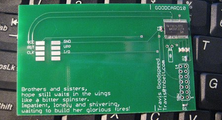
Here’s a quick prototype from [Travis Goodspeed]. It’s a smart card built around an MSP430 microcontroller. We’ve used the MSP430 in the past because of its low power demands. He says this business card currently supports 1.8V to 3.3V, but a future design will have 5V as well. Technologies like Java Card exist for running applets on smart cards, but a familiar microcontroller like the MSP430 could certainly make development much faster. Knowing [Travis], there’s a reader somewhere about to go through some serious fuzzing.

SIM Card Reader


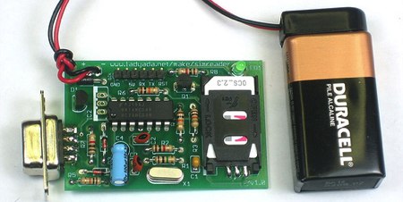
Adafruit Industries just announced their next kit: a SIM card reader. Using the kit, you can read or write any SIM card. You could use this for fun things like recovering deleted contacts and SMS messages. The kit looks like a very straight forward design (based on [Dejan]’s work); the only chip is a hex inverter and the board is powered by a regulated 9V battery. With all through-hole components, it should be easy to assemble. You can talk to it using the board mounted serial port or connect to the extra pin header using an FTDI USB cable just like the Boarduino. The FTDI option is bus powered, so you won’t need the battery. [ladyada] has collected some resources in case you want to learn more about smart cards.

Exposing And Photographing Silicon

Have you ever wanted to break open your IC and see where those pins really go? [nico] goes through his process of dissolving ICs to their core and photographing the tiny die. The technique involves liquefying the package in sulfuric acid until all the packaging material and pins are gone. He even explains how to use sodium bicarbonate (common baking soda) to neutralize the solution thus allowing for simple sink disposal. Although silicon hacking is generally done by funded hackers with a really nice lab, it is certainly possible to execute some of these techniques with limited equipment and chemical access. For instance, if you can’t get sulfuric acid, send your IC off to a failure analysis lab like MEFAS. For more information and stories on silicon hacking, check out [Chris Tarnovsky]’s process for hacking smartcards and [bunnie]’s talk Hacking silicon: secrets behind the epoxy curtain.

Silicon Hacking


Wired recently posted an article and video detailing our friend [Chris Tarnovsky]’s process for hacking smart cards. In the video, [Chris] shows how he strips away physical components of the chips inside the smartcards using various gadgets and chemicals.

The first step is to remove the chip from its plastic frame. After soaking it in acid for about 10 minutes, the epoxy is removed and the chip is exposed. After that the outer layer is loosened by soaking the chip in two solutions of acetone, the second being the “clean” one. Then the chip is placed on a hotplate where a drop of fuming nitric acid is applied with a dropper; the chip is washed again in an ultrasonic cleaner, removing any residue left.

[Chris] then returns the chip to the card. He will apply nail polish to act as a masking material. He scratches a hole through the polish with a needle held by a micro positioner in the area of interest. The hole is treated with hydrofluoric acid and then etched in short intervals until the desired layer of silicon is exposed. At this point, the card is fully prepped.

Now by powering the chip with the needle resting on the bus, [Chris] can read the code on the chip by sending it various commands and watching how it reacts. To see more of [Chris]’s reverse engineering work, check out Flylogic Engineering’s Analytical Blog. It’s a enjoyable read even if you’re new to silicon hacking.