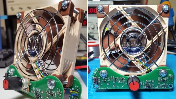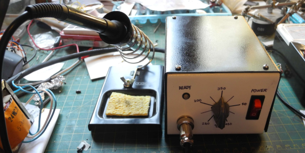
There is a certain sense of accomplishment one gets when building their own tools. This is what [Alejandro Velazquez] was going for when he built his own soldering station. Sure you can get a decent station for a pittance on Amazon, or eBay. You can even build your own microprocessor controlled station. [Alejandro] is currently interested in analog electronics, so he went that route to build his own closed-loop station.
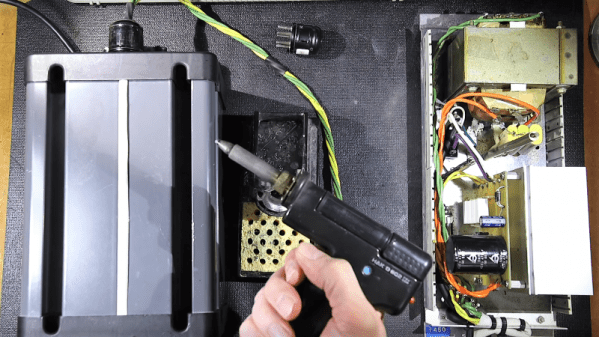
The handle is a 50 watt, 24-volt affair with a thermocouple. You can find this handle on many Hakko 907 clone soldering stations, often referred to as the 907A. The station itself is completely analog. A triac switches the current going to the heater. The triac is controlled by a PWM signal. The PWM itself is generated and regulated by an LM324 quad op-amp, which is the heart of the station. The op-amp compares the setpoint with the current temperature read from the soldering handle’s thermocouple, then adjusts the duty cycle of the PWM signal to raise, or lower the temperature.
It’s a classic control system, and the schematic is definitely worth checking out if you want to understand how op-amps can be used to create complex operations.
You can find plenty more information on analog electronics right here on Hackaday — we’ve covered thermocouple amplifiers, as well as instrumentation amps. If you’re more of a digital man, check out this Arduino controlled soldering station!