DIYing Huge BGA Packages

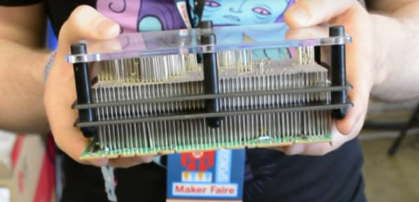
One day [Andy] was cruising around eBay and spotted something interesting. Forty Virtex-E FPGAs for two quid each. These are the big boys of the FPGA world, with 512 user IO pins, almost 200,000 logic gates, packed into a 676-ball BGA package. These are not chips designed for the hobbyist. These chips are not designed for boards with less than six layers. These chips aren’t even designed for boards with 6/6mil tolerances from the usual suspects in China. By any account, a 676-ball package is not like a big keep out sign for hobbyists. You don’t turn down a £2 class in advanced PCB design, though, leading to one of the most impressive ‘I just bought some crap on eBay’ projects we’ve seen.

halfbuilt
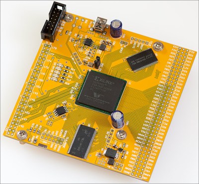
The project [Andy] had in mind for these chips was a generic dev board, which meant breaking out the IO pins and connecting some SRAM, SDRAM, and Flash memory. The first issue with this project is escape routing all the balls. Xilinx published a handy application note that recommends specific design parameters for the traces of copper under the chip. Unfortunately, this was a six-layer board, and the design rules in the application note were for 5/5mil traces. [Andy]’s board house can’t do six-layer boards, and their design rules are for 6/6mil traces. To solve this problem, [Andy] just didn’t route the inner balls, and hoped the 5mil traces would work out.

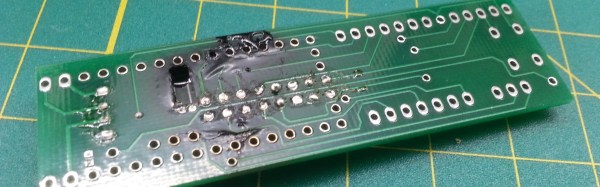
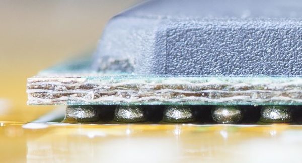
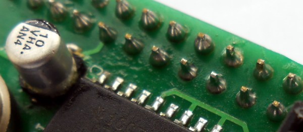
With 676 tiny little pads on a PCB, the clocks routed, power supply implemented, too many decoupling caps on the back, differential pairs, static RAM, a few LEDs placed just for fun, [Andy] had to solder this thing up. Since the FPGA was oddly one of the less expensive items on the BOM, he soldered that first, just to see if it would work. It did, which meant it was time to place the RAM, Flash, and dozens of decoupling caps. Everything went relatively smoothly – the only problem was the tiny 0402 decoupling caps on the back of the board. This was, by far, the hardest part of the board to solder. [Andy] only managed to get most of the decoupling caps on with a hot air gun. That was good enough to bring the board up, but he’ll have to figure some other way of soldering those caps for the other 30 or so boards.

Continue reading “DIYing Huge BGA Packages”

Ask Hackaday: How Hard Is It To Make A Bad Solder Joint?

When you learn to solder, you are warned about the pitfalls of creating a solder joint. Too much solder, too little solder, cold joints, dry joints, failing to “wet” the joint properly, a plethora of terms are explained  if you read one of the many online guides to soldering.

Unsurprisingly it can all seem rather daunting to a novice, especially if they are not used to the dexterity required to manipulate a tool on a very small-scale at a distance. And since the soldering iron likely to be in the hands of a beginner will not be one of the more accomplished models with fine temperature control and a good tip, it’s likely that they will experience most of those pitfalls early on in their soldering career.

As your soldering skills increase, you get the knack of making a good joint. Applying just the right amount of heat and supplying just enough solder becomes second nature, and though you still mess up from time to time you learn to spot your errors and how to rework and fix them. Your progression through the art becomes a series of plateaux, as you achieve each new task whose tiny size or complexity you previously thought rendered it impossible. Did you too recoil in horror before your first 0.1″ DIP IC, only to find it had been surprisingly easy once you’d completed it?

A few weeks ago we posted a Hackaday Fail of the Week, revolving around a soldering iron failure and confirmation bias leading to a lengthy reworking session when the real culprit was a missing set of jumpers. Mildly embarrassing and something over which a veil is best drawn, but its comments raised some interesting questions about bad solder joints. In the FoTW case I was worried I’d overheated the joints causing them to go bad, evaporating the flux and oxidising the solder. This was disputed by some commenters, but left me with some curiosity over bad solder joints. We all know roughly how solder joints go wrong, but how much of what we know is heresay? Perhaps it is time for a thorough investigation of what makes a good solder joint, and the best way to understand that would surely be to look at what makes a bad one.

Continue reading “Ask Hackaday: How Hard Is It To Make A Bad Solder Joint?”

PinJig Soldering Clamp Has Pins Seized By Airport Security

There’s an old adage that when performing a live demo, previously working hacks will mysteriously go awry. In this case, the hardware demo was doomed before it ever arrived at the conference.

PinJig is an interesting take on though-hole soldering. As its name indicates, it’s a jig which holds through-hole components in place as the board is flipped on its side (or even upside down). This is accomplished by 2000 steel pins which are locked in place after being nestled around all of the board’s components. Unfortunately, carrying this prototype onto an international flight didn’t work out. [Niall Barrett] told us that on his way from Ireland to Bay Area Maker Faire he was required to ditch the 3-inch steel pins that make up the jig, or not get on the plane.

Continue reading “PinJig Soldering Clamp Has Pins Seized By Airport Security”

Fail Of The Week: Where’s Me Jumper?

Just in case you imagine that those of us who write for Hackaday are among the elite of engineering talent who never put a foot wrong and whose benches see a succession of perfectly executed builds and amazing hacks, let me disabuse you of that notion with an ignominious failure of my own.

I was building an electronic kit, a few weeks ago. It’s a modular design with multiple cards on a backplane, though since in due course you’ll see a review of it here I’ll save you its details until that moment. In my several decades of electronic endeavours I have built many kits, so this one as a through-hole design on the standard 0.1″ pitch should have presented me with no issues at all. Sadly though it didn’t work out that way.

Things started to go wrong towards the end of the build, I noticed that the temperature regulator on my soldering iron had failed at some point during its construction. Most of it had thus been soldered at a worryingly high temperature, so I was faced with a lot of solder joints to go over and rework in case any of them had been rendered dry by the excessive heat.

In due course when I powered my completed kit up, nothing worked. It must have been the extra heat, I thought, so out came the desolder braid and yet again I reworked the whole kit. Still no joy. Firing up my oscilloscope I could see things happening on its clock and data lines so there was hope, but this wasn’t a kit that was responding to therapy. A long conversation with the (very patient) kit manufacturer left me having followed up a selection of avenues, all to no avail. By this time a couple of weeks of on-and-off diagnostics had come and gone, and I was getting desperate. Somehow I’d cooked this thing with my faulty iron, and there was no way to find the culprit.

Continue reading “Fail Of The Week: Where’s Me Jumper?”

It’s Time To Finally Figure Out How To Use KiCAD

KiCAD has been making leaps and bounds recently, especially since CERN is using it almost exclusively. However, while many things are the same, just enough of them are different from our regular CAD packages that it’s hard to get started in the new suite.

[Chris Gammell] runs Contextual Electronics, an online apprenticeship program which goes from concept to assembled electronics covering everything in between. To take the course you pay a nominal fee, but [Chris] posted a very excellent ten-part video series made during the last run of classes which you can watch without charge. The videos go through the basics of KiCAD while hitting the major points to consider when designing and manufacturing your electronics.

The project [Chris] chose is a simple circuit that blinks an LED with a 555. The first videos cover navigating KiCAD’s component schematic editor and library system. Next comes creating circuit schematics and component footprint creation. [Chris] covers PCB layout, the generation of Gerber files, and finally ordering the design from OSH Park — the purveyors of purple boards we’ve come to know and love. The series finishes up with simulating the circuit in LTSpice, ordering the parts, and finally soldering and debugging of the board. If all goes correctly you should now have a single blinking LED.

If the bright summer sun is burning your delicate skin, and you’d rather be locked inside with solder fumes, add this to your watch list now!

Continue reading “It’s Time To Finally Figure Out How To Use KiCAD”

Hackaday Links: May 22, 2016

Lulzbot’s TAZ 6 has been released. Lulzbot’s printers consistently place in the top three of any 3D printing list, and the TAZ 6 will likely be no exception. [James Bruton] was one of the lucky ones who got a review unit, and first looks are promising. The TAZ 6 has the auto bed leveling found in the Lulzbot Mini, and a ‘power tower’ for all the electronics. There are completely unconfirmed rumors (or someone told me and I forgot who) that the power tower will be available separately at some point.

The most impressive circuit we’ve seen this week month year is the dis-integrated 6502. It’s a discrete 6502 CPU, about a square foot in size. It’s slow, but it works. RAM and ROM is easy to make embiggened, which means someone needs to build a dis-integrated 6522 VIA. Who’s game?

[Jeremy Cook] wanted to learn another CAD package, in this case Onshape. Onshape is the ‘first cloud-only CAD package’, which has one huge bonus – you can run it anywhere, on anything – and one huge minus – it’s in the cloud. He designed a bicycle cupholder.

Last week, several thousand Raspberry Pi Zeros shipped out to retailers in the US and UK. For a time, Pi Zeros were in stock in some online stores. Now? Not so much. Where did they all go? eBay, apparently. It’s called arbitrage, and it’s the only risk-free form of investment.

Remember those ‘bed of nails’ toys, that were basically two sheets of plastic, with hundreds of small pins able to make 3D impressions of your face and hands. No, there is no official name for these devices, but here’s a Kickstarter for a very clever application of these toys. You can use them to hold through hole parts while soldering. Brilliant.

You should not pay attention to 3D printers on Kickstarter. Repeat after me: you should not give money to 3D printers on Kickstarter. Here’s a 3D printer on Kickstarter, promising a 3D printer for $74. I own several hats, and will eat one if this ships by next year.

Remember bash.org? It’s being reimplemented on hackaday.io.

An Affordable Ultrasonic Soldering Iron

One of the most interesting facets of our community of hackers and makers comes from its never-ending capacity to experiment and to deliver new technologies and techniques. Ample demonstration of this came this morning, in the form of [Hunter Scott]’s Hackaday.io project to create an ultrasonic soldering iron. This is a soldering technique in which the iron is subjected to ultrasonic vibrations which cavitate the surface of the materials to be soldered and remove any oxides which would impede the adhesion of the solder. In this way normally unsolderable materials such as stainless steel, aluminium, ceramic, or glass can be soldered without the need for flux or other specialist chemicals. Ultrasonic soldering has been an expensive business, and [Hunter]’s project aims to change that.

This iron takes the element and tip from a conventional mains-powered soldering iron and mounts it on the transducer from an ultrasonic cleaner. The transducer must be given an appropriate load which in the case of the cleaner is furnished by a water bath, or it will overheat and burn out. [Hunter]’s load is just a soldering iron element, so to prevent transducer meltdown he keeps the element powered continuously but the transducer on a momentary-action switch to ensure it only runs for the short time he’s soldering. The project is not quite finished so he’s yet to prove whether this approach will save his transducer, but we feel it’s an interesting enough idea to make it definitely worth following.

This is the first ultrasonic soldering project we’ve featured here at Hackaday. We have however had an ultrasonic plastic welder before, and an ultrasonic vapour polisher for 3D prints. It would be good to think this project could spark a raft of others that improve and refine DIY ultrasonic soldering designs.