DHT11 Humidity And Temperature Sensor Package

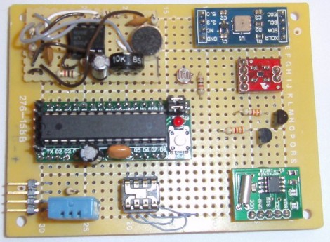
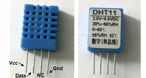
Temperature and humidity measurements are a nice addition to many hobby projects. But [Rajendra Bhatt] makes the point that many of these sensors have a price tag that is well above what most hobbiests are willing to spend. He decided to take an in-depth look at the DHT11 sensor; which you can get your hands on for under $3 if you know where to look.

The four-pin device uses a 1-wire protocol. [Rajendra] discusses the ins and outs of the communications, demonstrating the part using a PIC 16F628. It’s a snap to connect to your project, requiring VCC, GND, and a pull-up resistor on the single data line. We’ve already seen it used on at least one project, and hope to see more of this little guy in your own hacks.

Now we found this part listed on eBay for less than $3 (buy it now price including shipping… how can they do that?). But Octopart didn’t come up with any options. If you know how to get this through traditional parts suppliers let us know in the comments.

Over-engineering A Two-zone Thermometer

We love the extra touches that [Andrianakis Haris] added to his two-zone electronic thermometer. It includes features that you just wouldn’t find on a mass-market commercial product because of issues like added cost. For example, you can see that the PCB juts up above the LCD display, allowing the module to be mounted on a pair of screws thanks to the keyhole shape that was drilled in the substrate. I increases the board size greatly, but on a small hobby run this won’t usually affect the price of the board depending on the fab house pricing model.

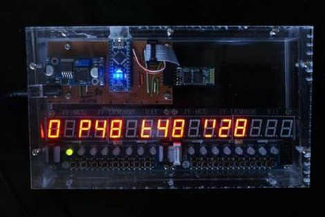
The design uses an ATmega8 microcontroller to monitor sensors in two different places. There is an onboard LM35 temperature sensor for monitoring the space where the unit resides. A remote sensor module uses a DHT-11 chip to gather data about temperature and humidity. That sensor is wired, but there is one wireless option for the device. Data can be pulled down from it via an optional Bluetooth module which can be soldered to a footprint on the back of the board.

Check out the video after the break to see temperature readings pulled down wirelessly. Continue reading “Over-engineering A Two-zone Thermometer”

ChipKIT Temperature Shield Supports A Dozen Sensors

chipkit_temp_board

[Will] wrote in to share a useful add-on he designed for the ChipKIT UNO 32, a 12-port temperature sensor board.

Constructed for one of his customers, the shield accepts any 2-wire 10k thermistor sensors, outputting the readings to a small LCD screen. The screen is supported by some code put together by his associate [crenn], but you are not limited to solely displaying the temperatures there. Since this module piggybacks on top of the ChipKIT the same fashion as any standard shield, you clearly have the ability to use and manipulate the data at will. With 12 ports on board this would work well for a house-wide temperature monitoring system, or perhaps in a complex brewing setup.

Both the temperature shield and LCD boards have been released under the Open Source Hardware License, so you can easily build your own if you have the means, though [Will] has a few extras he’s willing to sell if you need one quickly.

Throw Together A Temperature Logger In Minutes

[Rajendra] found an easy way to make a USB temperature logger. He already had a USB to UART adapter that takes care of the heavy lifting. On one end it’s got the USB plug, on the other a set of pins provide a ground connection, 3.3V and 5V feed, as well as RX/TX lines.

To get the hardware up and running all he needed was something to read a temperature sensor and push that data over the serial connection. An 8-pin microcontroller in the form of a PIC 12F1822 does the trick. It runs off of the 5V pin on the USB-UART, and uses the ADC to get temperature data from an MCP9701A sensor.

The sample rate is hard-coded into to the PIC’s firmware, but adding a button, or coding some serial monitoring could easily make that configurable. [Rajendra] used Processing to write an app which displays the incoming temperature info and uses the computer to time-stamp and log the inputs. We could see this as a quick solution to tracking wort temperature during fermentation to make sure your beer comes out just right.

Adding Fluke 54 II Features To A 51 II Thermometer

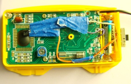
The difference between Fluke’s 54 II and 51 II thermometers is the addition of a second channel for dual temperature sensing, and buttons which control data logging. Oh, and an additional $150 in price for the higher model. [TiN] was poking around inside and with the help of some forum members he figured out how to unlock additional features on his low-end Fluke temperature meter. You can do the same if you don’t mind cracking open the meter, sourcing and soldering most of the components seen above, cutting holes in the case for the buttons, and hoping it still works when you put everything back together.

It seems that Fluke designed one full-featured unit and watered it down to fill a hole in the lower-priced market just like some other testing-hardware manufacturers (Rigol’s digital storage oscilloscopes come to mind). But the MSP430 P337I in this meter cannot be reflashed, so this would most likely be unhackable hardware if the firmware for the two models is different. After some intensive study of the PCB layout [TiN] found a set of resistors which seemed to serve no external hardware purpose. They do connect to the microcontroller and together they create a two-bit code. He was able to get pictures of the four different hardware models and work out which resistor combinations identify the different meters. Now he can get the firmware to believe it is operating a Fluke 54 II, the rest is just putting the correct passive components onto the unpopulated locations.

We think the quest is what is of interest with this hack. [TiN] did an amazing job of photographing and writing about each step in the process. We’re unlikely to try this ourselves but loved reading about it.

Keep All Eyes On Your Kegerator With This Light Up Gauge Cluster

kegerator_gauge_cluster

A few years back [Evan] built a kegerator from a mini fridge and was quite happy with his new beer chiller. Like many of us do, he started thinking up ways in which he could improve the project as soon as it was completed. While it took a couple of years, he recently got around to adding the temperature and capacity gauges he always wanted.

He added a temperature probe to the refrigerator, and then constructed a pair of tools that he could use to measure how much beer was left in the keg. The volume monitors include a scale built using a pair of pressure sensors from SparkFun, and a flow sensor installed in the beer line.

[Evan] scored an old Chevy gauge cluster and cleaned it up before installing a pair of analog meters which he used to show the keg’s temperature and “fuel” level. Since he feels no project is complete without some LED love, he added a few of them to the display without hesitation. The LEDs calmly pulsate when the keg sits idle, but spring to life and begin flashing when the flow sensor is activated.

As evidenced by this pair of keg monitoring systems, we think that you can never have enough information when it comes to your beer stash, so we really like how this project came together.

Be sure to check out his kegerator’s gauge cluster in the video below.

Continue reading “Keep All Eyes On Your Kegerator With This Light Up Gauge Cluster”

Electronic Bird House Monitoring Goes A Few Steps Further

[Stephen Albers] offers his avian friends a lot of extras with this electronically monitored bird house. This will not only give you a look at what’s going on inside, but provide a source for several other bits of data as well.

First off, a camera has been mounted to the underside of the roof. This looks down on the nesting area and features night vision so that you can peek in any time day or night. He used a WiFi webcam that operates separately from the other electronics.

With the remainder of the setup he is able to harvest temperature and humidity data inside, temperature outside, force on the bottom of the house (although this turned out to be less useful than anticipated), and a in-and-out count for the doorway provided by an IR transmitter/receiver pair.

This offers quite a bit more than the last bird house project we saw. That one also left a lot to be desired as far as protecting the electronics. [Stephen] didn’t skip on that kind of protection. Most of the electronics are housed in an acrylic chamber in the base of the house. The sensors find themselves nestled in plastic enclosures, although some work needs to be done to ensure that the temperature and humidity sensors will still function correctly with this setup.