Robotically-Tuned Tube Radio

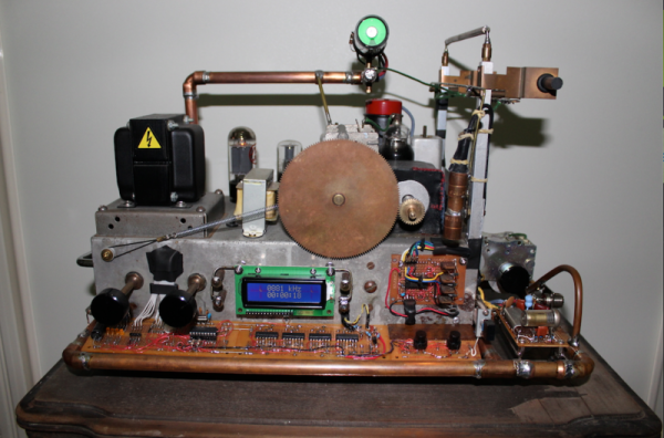
Dubbed the “Robot Radio” by [Brek], this clinking-&-clunking project merges three generations of hackers’ favorite technologies: robots, vacuum tubes, and microcontrollers. After the human inputs the desired radio frequency the machine chisels its way through the spectrum, trying its best to stay on target.

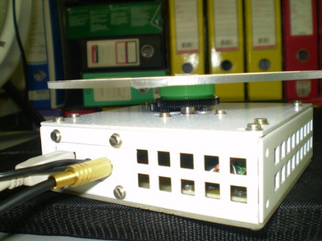
This build began its life as a junky old tube radio that [Brek] pulled out of a shed. The case was restored and then the hacking began. Inserted between the human and the radio, a PIC 16F628A keeps watch in both directions. On one side, the radio’s tank circuit is monitored to see what frequency the radio is currently playing. On the other, the human’s input sets a desired frequency. If the two do not match, the PIC tells a stepper motor to begin cranking a pair of gears until they do.

Another interesting feature is that as the tubes and other electronics warm up and change their values, the matching circuit will keep them in line. [Brek] shows this in the video by deliberately sabotaging the gears and seeing the robot adjust them back where they belong.

As an afterthought, the Robot Radio was supplemented with a module that adds 100khz to the signal so that the information from a nearby airport can be received.

[Brek] styled the whole machine up with some copper framing and other bits, similar to his spectacular atomic clock build we featured last month.

See the video of the radio tuning after the break.

Continue reading “Robotically-Tuned Tube Radio”

Automated Turntable Photography

[Muris] has a friend who is selling items on the internet. This friend wanted a simple way to make rotating images of the products and asked him to help. The result of his labors is this base unit that drives the turn table and controls the camera.

The first iteration of the turntable was powered by the stepper motor from a floppy drive. A disc was mounted directly on the motor spindle, but the results were a bit poor. This is because the motor had a fairly low resolution of 200 steps per rotation. That doesn’t allow for smooth animation, and there was a lot of vibration in the system. An upgrade to the geared system you see above included swapping out that motor for one from an old scanner. Now it achieves 1200 steps per rotation and the vibration is gone.

The connectors seen in the base are USB, incoming power, and shutter control. [Muris] wrote a program to control the PIC 16F628A inside the base. The program sends commands via USB and has parameters for number of frames per rotation, direction of rotation, and the like. Set it up as desired, place the product on the turntable, and hit start. Unfortunately there’s no video of this in action because [Muris] gave it to his friend as soon as it was finished. We guess the fact that he didn’t get it back means it’s working great.

If you don’t mind some rough edges and exposed wiring you can throw a system of your own together pretty quickly.

Polish Your Understanding Of Capacitors By Building This Meter

Building a capacitance meter is a great exercise. If you’re feeling quite safe in your digital-circuit-only life, this will push just far enough out of the comfort zone for you to see there’s nothing to fear in adding analog circuits to your designs. Here, [Raj] compares a voltage divider and RC timer to calculate the value of a capacitor. The project is aimed at teaching the concepts, and will be easy to follow for anyone who has at least a bit of experience working with a programmable microcontroller.

The meter is based on an established equation that uses are starting and ending voltage, as well as the time it took to transition between the two, to calculate capacitance. The capacitor will be charged from 0 volts to 0.5 volts. Using the built-in analog comparator is the easiest way to do this. [Raj] breadboarded a voltage divider to establish a 0.5V reference on one of the comparator’s pins. The other input comes from a circuit that places a resistor in line with the capacitor being tested. When that reading rises above the 0.5 volt reference the comparator match will be tripped, stopping a timer that had been running during the charge cycle. From there it’s just a matter of using the timer value in the calculation.

DHT11 Humidity And Temperature Sensor Package

Temperature and humidity measurements are a nice addition to many hobby projects. But [Rajendra Bhatt] makes the point that many of these sensors have a price tag that is well above what most hobbiests are willing to spend. He decided to take an in-depth look at the DHT11 sensor; which you can get your hands on for under $3 if you know where to look.

The four-pin device uses a 1-wire protocol. [Rajendra] discusses the ins and outs of the communications, demonstrating the part using a PIC 16F628. It’s a snap to connect to your project, requiring VCC, GND, and a pull-up resistor on the single data line. We’ve already seen it used on at least one project, and hope to see more of this little guy in your own hacks.

Now we found this part listed on eBay for less than $3 (buy it now price including shipping… how can they do that?). But Octopart didn’t come up with any options. If you know how to get this through traditional parts suppliers let us know in the comments.

Three Digit Binary Clock

Here’s a three digit binary clock that [Viktor] designed. It uses a multiplexed display to drive one digit at a time with a PIC 16F628A. The video after the break shows it ticking away, display hours, minutes, and seconds in blue LEDs. You may be wondering why those LEDs are not flush to the board? [Viktor] took the project one step further than most binary clock projects, designing a PCB to fit into the enclosure of an old laptop PSU and then having the board manufactured. With options like DorkbotPDX groups orders its has become quite inexpensive to do this and it’s really good practice for when you need to design a highly complicated board for that super-fantastic project of the future.

Continue reading “Three Digit Binary Clock”

Wristwatch Board With Throwback Digits

This wristwatch circuit board has some pretty interesting digits. They’re older components that give a classic look to your wristwatch display. On board you’ll find a PIC 16F628A running with an external clock crystal. The display isn’t always illuminated (kind of like Woz’s watch) in order to save the batteries, but can be woken up for a short time with the push of a button. The steam-punk-ish body seen to the left is the just first try. This guy has four more boards left so it should be fun to see what he comes up with.

[Via Hackaday Flickr Pool]

Modem Used In An Alarm System

This alarm system senses motion and then alerts you by phone. [Oscar] had an old external modem sitting around and, with some wise hardware choices, he came up with a simple circuit to use it. First up is the PIC 16F628A chosen because it doesn’t require an external crystal. This connects with the modem via a DS275 RS232 transceiver because it requires no external parts for connection. The final portion of the puzzle is a PIR sensor that triggers a pin interrupt in the sleeping PIC, which then dials your number to alert you. It doesn’t look like anything happens other than your phone ringing, but that’s enough for a simple system. We’re just happy to see how easy it was to use that modem… time to go hunting for one in dreaded junk trunk. Don’t miss the clip after the break.

Continue reading “Modem Used In An Alarm System”