What If Tinkercad Was Self-Hosted?

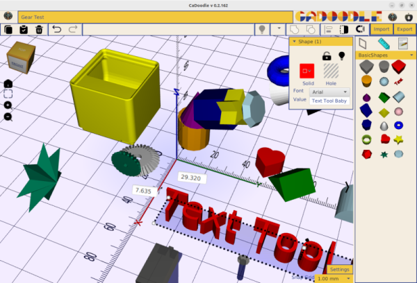
While we use a lot of CAD tools, many of us are fans of Tinkercad — especially for working with kids or just doing something quick. But many people dislike having to work across the Internet with their work stored on someone’s servers. We get it. So does [CommonWealthRobotics], which offers CaDoodle. It is nearly a total clone of Tinkercad but runs on Windows, Linux, Mac, or even Chrome OS.

Is it exactly Tinkercad? No, but that’s not always a bad thing. For example, CaDoodle can work with Blender, FreeCAD, OpenSCAD, and more. However, on the business end, it sure looks like the core functions of Tinkercad.

The program appears fairly new, so you have to make some allowances. For example, the Linux AppImage seems to have difficulty loading plugins (which it needs to import many of its file formats). In addition, on at least some systems, you have to resize the window after it starts, or it won’t respond. But, overall, it is pretty impressive. The Settings, by the way, has a checkbox for advanced features, and there are some other goodies there, too.

One reason we found this interesting is that we sometimes go into schools, and they don’t want us to have kids on the Internet. Of course, they don’t like us installing random software either, so you can pick your battles.

Tinkercad, of course, continues to add features. Not all of which you’d expect in a drawing package.

Tinkercad In Color

Tinkercad is famous for having lots of colors in the interface. But once you export an STL, that file is notoriously monochrome. If you are printing with a single color printer, no problems. But if you have a color printer, what do you do? [CHEP] shows some options, including a relatively new one, in the video below.

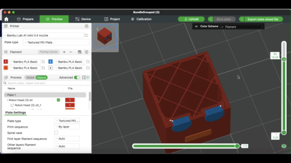
The simple way is to “paint” the STL inside your slicer. But as [CHEP] shows, that is a pain and also has some undesirable side effects. A better approach is to export each part (or, at least, each part of the same color) into separate STL files, which you can then import together in the slicer. You still have to paint, but you don’t have to select different faces, and the resulting coloring is more what you’d expect.

Continue reading “Tinkercad In Color”

Tinkercad Continues To Grow Up

It is easy to write off Tinkercad as a kid’s toy. It is easy enough for kids to learn and it uses bright colors looking more like a video game than a CAD tool. We use a variety of CAD tools, but for something quick, sometimes Tinkercad is just the ticket. Earlier this year, Tinkercad got a sketch feature, something many other CAD programs have and, now, you can even revolve the sketch to form complex objects. Tinkercad guru [HL ModTech] shows you how in the video below.

It wasn’t long ago that we needed to cut an irregular shape out of an STL and we found the sketch feature which was perfect for that purpose. If you’ve used other CAD tools, you’ll know that sketches are typically 2D shapes that get changed into a 3D shape. The traditional thing is to simply extrude it, so if you draw a circle in 2D, you get a cylinder.

Continue reading “Tinkercad Continues To Grow Up”

Using A 2D Scanner To Make 3D Things

[Chuck Hellebuyck] wanted to clone some model car raceway track and realised that by scanning the profile section of the track with a flatbed scanner and post-processing in Tinkercad, a useable cross-section model could be created. This was then extruded into 3D to make a pretty accurate-looking clone of the original part. Of course, using a flatbed paper scanner to create things other than images is nothing new, if you can remember to do it. A common example around here is scanning PCBs to capture mechanical details.

The goal was to construct a complex raceway for the grandkids, so he needed numerous pieces, some of which were curved and joined at different angles to allow the cars to race downhill. After printing a small test section using Ninjaflex, he found a way to join rigid track sections in curved areas. It was nice to see that modern 3D printers can handle printing tall, thin sections of this track vertically without making too much of a mess. This fun project demonstrates that you can easily combine 3D-printed custom parts with off-the-shelf items to achieve the desired result with minimal effort.

Flatbed scanner hacks are so plentiful it’s hard to choose a few! Here’s using a scanner to recreate a really sad-looking PCB, hacking a scanner to scan things way too big for it, and finally just using a scanner as a linear motion stage to create a UV exposure unit for DIY PCBs.

Continue reading “Using A 2D Scanner To Make 3D Things”

Hinged Parts For The 8th Grade Set

I recently agreed to run a 3D printing camp for 8th graders. If you’ve never shared your knowledge with kids, you should. It is a great experience. However, it isn’t without its challenges. One thing I’ve learned: don’t show the kids things that you don’t want them to try to print.

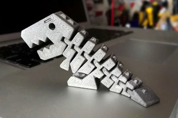
I learned this, of course, the hard way. I have several “flexy”3D prints. You know the kind. Flexy dinosaurs, cats, hedgehogs, and the like. They all have several segments and a little hinge so the segments wobble. The problem is the kids wanted to print their own creations with flexy hinges.

I’ve built a few print-in-place hinges, but not using Tinkercad, the software of choice for the camp. While I was sure it was possible, it seemed daunting to get the class to learn how to do it. Luckily, there’s an easy way to add hinges like this to a Tinkercad design. There was only one problem.

Continue reading “Hinged Parts For The 8th Grade Set”

Parametric Design With Tinkercad

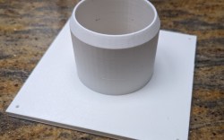
Tinkercad is like the hamburger helper of 3D design. You hate to admit you use it, and you know you should put in more effort, but — darn it — it’s easy, and it tastes pretty good. While I use a number of CAD programs for serious work, sometimes, when I just want a little widget like a flange for my laser cutter’s exhaust, it is just easier to do it in a few minutes with Tinkercad. However, I heard someone complaining the other day that it wasn’t of any use anymore because they took away custom shape generators. That statement is only partially true. Codeblocks allow you to easily create custom parametric items for use in Tinkercad.

A Tinkercad-designed flange

There was a time when you could write Javascript to create custom shapes, and it is true that they removed that feature. However, they replaced it with Codeblocks which is much easier to use for their target audience — young students — and still very powerful.

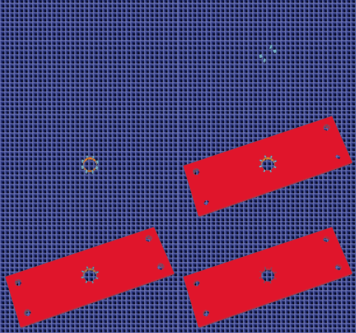
If you’ve used parametric design in a professional package or even used something like OpenSCAD, you probably don’t need to be sold on the benefit. This is, of course, a simple form of it, but the idea is to define things as mathematical relationships. As an example, suppose you have a front panel with two rows of four holes for switches evenly spaced and centered. That would be easy to draw. But if you later decide the top row needs five holes and the bottom only needs three, it will be a fair amount of work. But if you have the math defining it right, you change a few variables, and the computer does the rest. Continue reading “Parametric Design With Tinkercad”

Tinkercad Gets A Move On

Going to the movies is an experience. But how popular do you think they’d be if you went in, bought your popcorn, picked your seat, and the curtain would rise on a large still photograph? Probably not a great business model. If a picture is worth 1,000 words, then a video is worth at least a million, and that’s why we thought it was awesome that Tinkercad now has a physics simulator built right in.

Look for this icon on the top right toolbar.

It all starts with your 3D model or models, of course. Then there’s an apple icon. (Like Newton, not like Steve Jobs.) Once you click it, you are in simulation mode. You can select objects and make them fixed or movable. You can change the material of each part, too, which varies its friction, density, and mass. There is a play button at the bottom. Press it, and you’ll see what happens. You can also share and you have the option of making an MP4 video like the ones below.

We, of course, couldn’t resist. We started with a half-sphere and made it larger. We also rotated it so the flat side was up. We then made a copy that would become the inside of our bowl. Using the ruler tool, we shaved about 2 mm off the length and width (X and Y) of the inner sphere. We also moved it 2 mm up without changing the size.

Using the alignment tools, you can then center the inner piece in the X and Y axis. Change the inner color to a hole and group the objects. This forms a simple bowl shape. Then we moved the workplane to a random part of the inner surface of our bowl and dropped a sphere. Nothing complicated.

Continue reading “Tinkercad Gets A Move On”