Make Your Own Custom IPhone Back Glass

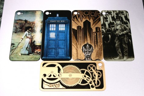
[Jake von Slatt] is at it again; putting his own artistic spin on ordinary items. This time around it’s the glass on the back of an iPhone. It kept breaking and after a few replacements he wanted to try to replace the glass with a piece of etched brass. But part way through that experiment, he figured out how to use toner transfer to develop these stunning custom iPhone glass back plates.

The first step is to source the correct replacement back for your phone. These are made of two parts, the glass and a plastic backer. By carefully heating and wedging the two parts with some popsicle sticks he was able to separate the pieces. Next, he cleans and buffs the glass, preparing it for the artwork he is about to apply. Toner transfer paper, just like that used for PCB resist, is used to print and adhere a design to the underside of the glass. From there he hand paints over the black outline to achieve the results seen above.

It takes time and patience, but shouldn’t be any harder than etching a circuit board.

PCB Manufacturing Tutorial

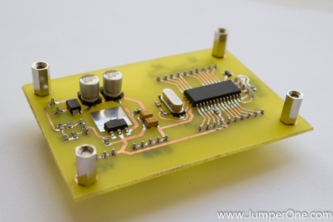
There comes a time in every maker’s career where solderless breadboards won’t do, perfboard becomes annoying, and deadbug is impossible. The solution is to manufacture a PCB, but there’s a learning curve. After learning a few tricks from [Scott]’s awesome DIY PCB guide, it’s easy to make your own printed circuit boards.

There are a few basic steps to making a PCB. First is designing the board in Eagle or KiCad. The next step, putting the design into copper, has a lot of techniques to choose from. Photo transfer, direct printing, and CNC milling have huge benefits, but by far the most common means hobbyists produce boards is with toner transfer using a laminator.

Unless you’re doing SMD-only circuits, a drill is required. Most people can get away with a Dremel or other rotary tool, but Hackaday has a favorite drill press that is perfect for drilling holes in FR-4. In part two of [Scott]’s tutorial, he goes over solder masks, silk screens before jumping into vias. These small bits of copper conducting electricity through a circuit board are extremely hard for the garage-bound builder to achieve on their own, but there are a few solutions – copper rivets (anyone have a US source for these?) and copper foil can be used, but sometimes the most effective solution is just hitting the board with a lot of solder and heat.

Thanks [Upgrayd] for the title pic.

Etching Your Own Boards Really, Really Fast

Sometimes the planets align and the Hackaday tip line gets two posts that are begging to be used together. Here’s two hacks to etch your own boards at home in just a few minutes.

Toner transfer PCBs on the quick

One way of putting an etch mask on a PCB is with the toner transfer method: print your circuit on a piece of inkjet photo paper using a laser printer, lay that circuit face down on a sheet of copper, and go at it with a clothes iron. This takes a heck of a lot of time and effort, but [Dustin] found another way. He used parchment paper instead of inkjet photo paper. Once the paper was on the board, he rolled it through a laminator. The results are awesome. It’s a very fast process as well – you don’t need to soak your board in water to get the photo paper off.

Etching that’s like wiping the copper away

[Royce] wrote in from the Milwaukee Makerspace to tell us about [Tom]’s etching process that is like wiping the copper off the board.  He used Muratic (Hydrochloric) acid and Hydrogen Peroxide with a sponge to wipe that copper away. The trick in this, we think, comes from the 30% H202 [Tom] picked up at a chemical supply company, but we’re pretty sure similar strengths can be purchased from beauty supply stores. Check out the video after the break to see [Tom] etch a 1 oz. board in just a few seconds.

Continue reading “Etching Your Own Boards Really, Really Fast”

Etching Your Own PCBs

When [Adr1an] wrote in to share a link to his PCB etching tutorial he mentioned that he knew we had already covered a ton of these guides. He’s absolutely right, not only have we featured a great number of them, but we also wrote our own quite a while ago. But that doesn’t mean we ignore them when they come in on the tips line. In fact, we read all of them that have something to offer and are pleased to feature the ones that are well presented… like this one!

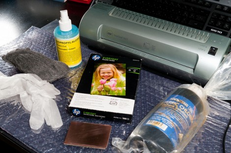
[Adr1an] went all out with his writeup. He not only covers all of the elements that go into this, but discusses where to purchase them and his thoughts on how he arrived at the choice. He’s using the toner transfer method and prefers Brother branded toner for its coverage and resistance to over-etching. He prints on HP Everday Photopaper, then uses a laminator to transfer to the copper clad board. For this guide he used 2oz copper but prefers 1oz copper as it etches faster. His etchant of choice is Ferric Chloride, which can be ordered as a dry powder. He uses the direct etch method of loading etchant into a sponge an applying that to the board.

The board he makes in the guide looks great, and it only took him 28 minutes!

Quick And Easy DIY PIC Development Board

diy_pic_dev_board

A few months back, [Phil] was looking to get into PIC development, but he couldn’t seem to find a simple development board for the PIC16F883 microcontroller he wanted to use. Since no retail offering had exactly what he was looking for, he decided to put together a dev board of his own.

He spent a couple hours in Eagle, putting together a simple board layout. [Phil] then busted out the iron and copper clad, making his dev board a reality using the tried and true toner transfer method.

He says that the board itself is quite simple, consisting of little more than the PIC, an LM1117 linear voltage regulator, and all the pin headers you could possibly need. While very basic and not necessarily a hack, we do like seeing people make their own tools when the market doesn’t provide what they want.

If you have been looking around for a simple PIC development solution, be sure to swing by [Phil’s] site – all of the schematics and layout files are free for the taking.

Test Your Etching Chops With PCB Map Making

pcb_map

[Martin] had been using standard perf board for most of his electronics projects, but as he was starting to utilize more surface mount ICs, he quickly realized that it was time to start making his own PCBs. Having never etched any PCBs using the toner transfer method, he figured it was as good a time as any to give it a try.

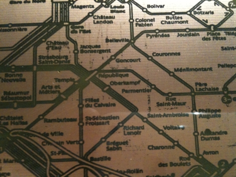
Rather than make a board for a particular project, he decided to try his hand at etching a very detailed map of the Paris Metro as a test pattern instead. He grabbed a large image of the subway map, then printed it out on the back of a supermarket flyer. He attached it to his PCB and ran it through a lamination machine to transfer the toner. He figured that the laminator would be easier than an iron to use, and was right for the most part. The only issue he had was that the laminator did not generate enough heat, so he supplemented the its heat output with a hair dryer.

When everything was said and done, he had a pretty good looking PCB on his hands. Most of the Metro tracks and text came out just fine, though he admits there is a bit of room for improvement. It looks nice when mounted in a frame, though we would love to see a functional circuit made out of a PCB map like that. Heck, we’d even settle for a double-sided PCB with a street-level map on one side an the Metro on the other!

Tuesday Two-Fer: Battery Cases And ABS Lettering

These are both interesting, unrelated, and can’t quite stand on their own so we threw them into one post.

On the left you see the product of using toner transfer on ABS plastic. [Bogdan] tried this out as a way to make front panels for his enclosures. It really shouldn’t work very well because ABS has a lower melting point than toner does. But it seems that it takes a while for the ABS to heat up. If you’re quick, ironing for about 10 seconds, you can get the toner to stick to the plastic and then soak the paper off, leaving your printed design looking nice and clean.

To the right you see a printed battery case. [Nikolaus Gradwohl] ran across the same problem we’ve face many times: how to attach batteries to your projects? We’ve duct-taped them together, used the blister packs they’re sold in, Dremeled them out of thrift-store toys and just about every other thing you can imagine. He decided to make them easy to manufacture with a 3D-printer. This is accomplished with an OpenSCAD file he wrote. Plug in the size and number of batteries and a printable package will be automatically generated.