Sometimes you wanna test a piece of USB hardware, but you don’t just want to plug it into a random old phone charger. [KS-Elektronikdesign] has whipped up a useful tool for just that case, allowing one to easily power USB hardware from a common bench supply.
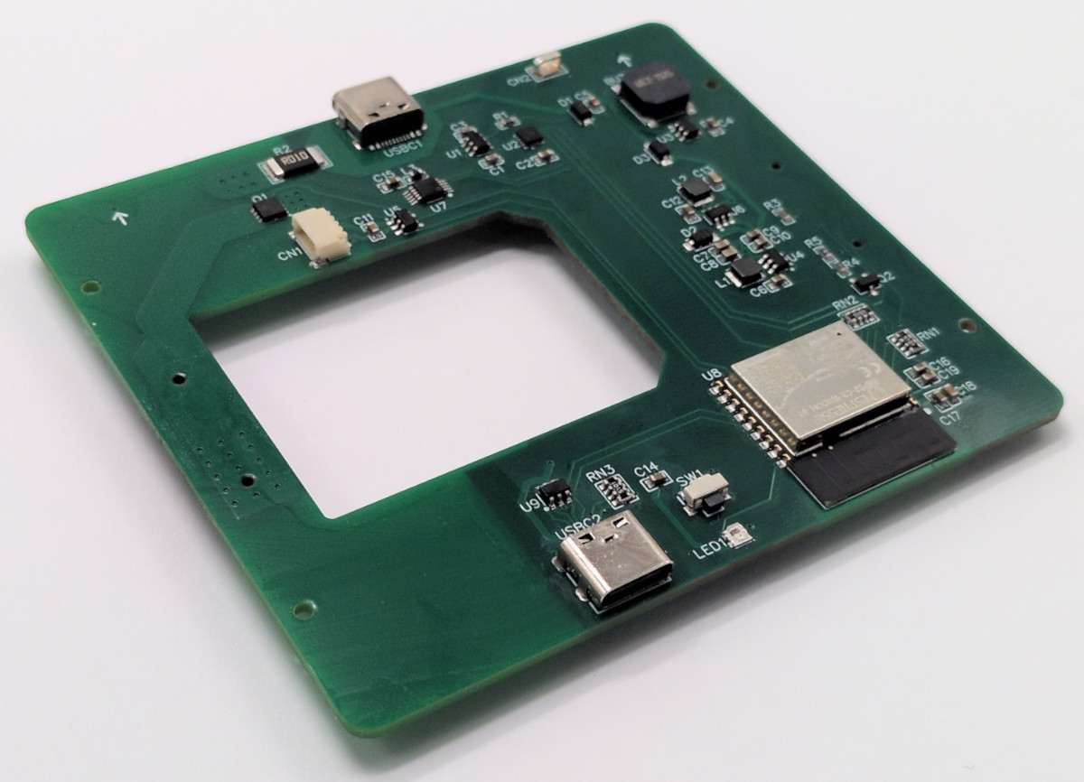
It would have been simple enough to whip up an adapter board to connect banana jacks to the power pins of a regular USB port. Easing the hookup process was indeed a part of the motivation for this project, in making it easy to power hardware that hooks up via USB-A and USB-C. However, it also goes a little further. It includes TUSB319 chip to handle the all-important power negotiation, without which many USB devices will not feel confident drawing their required amount of current.
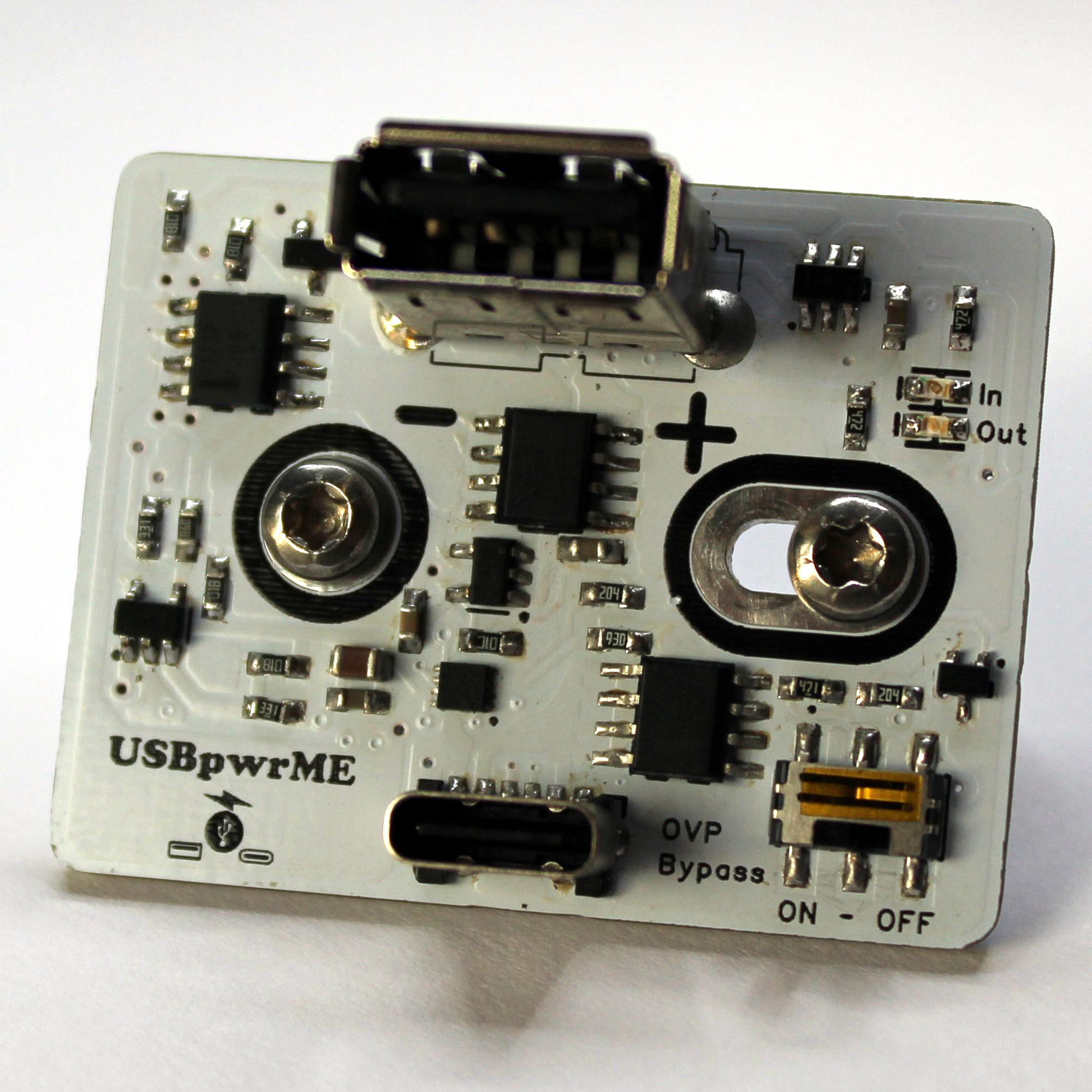 There is also polarity protection and over-voltage protection to stop you from blowing stuff up if you hook the board up wrong, which might save you a smartphone or three in the lab. The board will allow negotiated output power up to 10 W via USB-A and 15 W via USB-C, which isn’t heaps, but will be fine for lots of smaller devices. You can up that to 25 W and 35 W respectively if the board is switched to pass-through mode. We particularly like the physical design—the board will plug straight into the banana plugs on any supply with a jack spacing of 19 to 23 mm.
Overall, this is a useful tool to have in the lab if you want to run USB hardware with the flexibility of the voltage and current limits available on your bench supply. There are other ways to power modern USB devices, too, and you can do all kinds of wild stuff if you learn about USB PD and USB PPS. If you’re working up your own nifty lab tools for similar purposes, we’d love to know about it on the tipsline.