An ESP32 Dev Board As A Framework Laptop Module

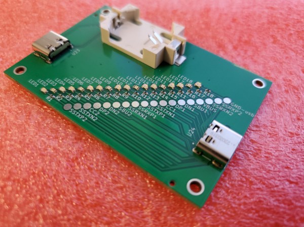
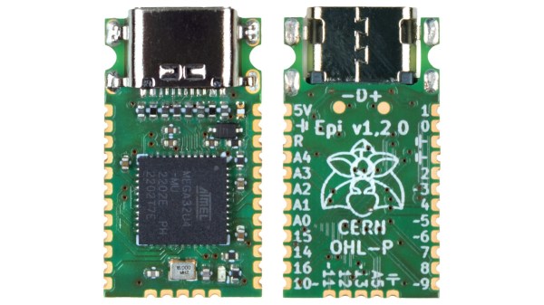
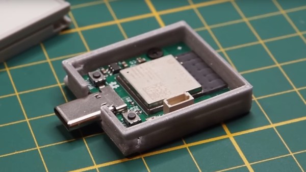
The Framework laptop will no doubt already have caught the eye of more than one Hackaday reader, as a machine designed for upgrade and expansion by its users. One of its key features is a system of expansion modules. The modules are USB-C devices in a form factor that slides into the expansion bays on the Framework Laptop. Framework encourages the development of new modules, which is something [Spacehuhn] has taken on with an ESP32-S3 development board.

The board itself is what you’d expect, the ESP is joined by a multicolor LED and one of those Stemma/Quiik connectors for expansion. The case is handily provided by Framework themselves, and all the files for the ESP32 module can be found in a GitHub repository. We’re guessing it will find application in experimenting with WiFi networks rather than as a standalone microcontroller. Either way, it shows the route for any Framework owners into making their own add-ons. Take a look, we’ve placed the video below the break.

As you might expect we’ve given a lot of coverage to the Framework laptop since its launch, in particular, our colleague [Arya Voronova] is a fan and has shown us many alternative uses for the parts.

Continue reading “An ESP32 Dev Board As A Framework Laptop Module”

JITX Spits Out Handy USB Cable Tester

When USB first came on the scene, one of the benefits was that essentially any four conductors could get you to the point where you could send information at 12 Mbps. Of course everything is faster these days, and reaching today’s speeds requires a little bit more fidelity in the cables. This simple tester makes sure that your modern cables are actually up to the task.

One of the design goals of this project is to automate away the task of testing cables or finding one that works, especially before thinking a problem with a device is somewhere in software, spending hours or days debugging, before realizing that it’s actually being caused by a hardware malfunction. The small PCB has two USB-C fittings to plug in both of the ends of a cable to, and between those connectors there is a number of LEDs. Each LED is paired to one the many conductors within the USB cable, and not only does it show continuity of these conductors but it can also show a high resistance connection via a dimly-lit or off-color display from an LED.

One of the other interesting facets of this build is the use of JITX, which is a software-defined electronics CAD tool which allows PCB design to be automated by writing out the requirements of the PCB into code, rather than drawing it manually. It’s worth a look, and a lot of the schematics of this particular project as well as some discussion on this software can be found on the project’s GitHub page. Incidentally, if this tester looks familiar, it’s probably because your’re thinking of the open source hardware USB tester created by [Ɓlvaro Prieto].

GaN Charger Teardown Reveals Value Of This New Technology

Every so often, a new technology comes along that offers a broad range of benefits over what we already have. Just as lithium-ion batteries have made nickel-cadmium cells boring and old hat, gallium nitride semiconductors are making silicon parts look unimpressive by comparison. [Brian Dipert] looked at what this means in a practical sense by tearing down a GaN phone charger.

The charger in question is a 30 watt USB-C charger produced by Voltme. It cost [Brian] just $10, as prices of GaN hardware have come down significantly as economies of scale have kicked in. The charger measures just 1.2×1.3×1.2 inches, and weighs only 1.5 ounces. That compact size is thanks to GaN semiconductors, which are able to run cooler at higher power levels than their silicon forebearers.

Cracking into the charger required levering open the case. The back panel came off with some work, revealing the mains terminals, which deliver AC power to the PCB inside via the case holding them in contact. Interestingly, the entire circuit inside is filled with an adhesive thermal goop, which helps pass heat from the hottest components to the charger’s case. [Brian] is able to guide us through the circuit, and he identified many of the major components. However, some of the markings on chips were beyond his research skills, and he asks any knowing readers to contribute their own information.

It’s interesting to see just what makes the high-powered compact chargers of today tick. Plus, it’s a hallmark of progress that what was once considered a wonder material can now be had in a $10 commodity phone charger from Amazon. How times change!

A Mega-Tiny Arduino

Integrated circuits, chipsets, memory modules, and all kinds of other transistor-based technology continues to get smaller, cheaper, and more energy efficient as time moves on. Not only are the components themselves smaller, but their supporting infrastructure is as well. Computers like the Raspberry Pi are about the size of a credit card and have computing power on the order of full-sized PCs from a few decades ago. The Arduino is no exception to this trend, either, and this new dev board called the Epi 32U4 might be the smallest ATmega platform we’ve seen so far.

As the name suggests, the board is based around the ATmega32U4 which is somewhat unique among Atmel chips in that it includes support for USB within the chip itself rather than relying on external translating circuitry. This makes it an excellent choice for any project which involves sending keyboard, mouse, or other peripheral information to a computer. This goes a few steps further with eliminating “bloat” compared to other boards, too — there’s no on-board voltage regulator, and just a single LEDs on pin 13.

One of the other features this board boasts over other small form factor boards is on-board USB-C, which is definitely a perk as more and more devices switch away from the various forms of older USB-type plugs. The project’s specifications are also available on this GitHub page for anyone that wants to produce their own. And, if you don’t have a 32U4 on hand and still want to build a keyboard project, it’s possible to get some other Arduinos to support these features but it’ll take a little more work.

Thanks to [Rasmus L] for the tip!

All About USB-C: Replying Low-Level PD

Last time, we configured the FUSB302 to receive USB PD messages, and successfully received a “capability advertisement” message from a USB-C PSU. Now we crack the PD specification open, parse the message, and then craft a reply that makes the PSU give us the highest voltage available.

How did the buffer contents look, again?

>>> b
b'\xe0\xa1a,\x91\x01\x08,\xd1\x02\x00\x13\xc1\x03\x00\xdc\xb0\x04\x00\xa5@\x06\x00<!\xdc\xc0H\xc6\xe7\xc6\x00\x00\x00\x00\x00\x00\x00\x00\x00\x00\x00\x00\x00\x00\x00\x00\x00\x00\x00\x00\x00\x00\x00\x00\x00\x00\x00\x00\x00\x00\x00\x00\x00\x00\x00\x00\x00\x00\x00\x00\x00\x00\x00\x00\x00\x00\x00\x00\x00'

The zeroes at the end might look non-significant, and they indeed are not with 99.99% certainty – that said, don’t just discard the entire tail end; one of the bytes in the beginning encodes the length of the message. We’ll read those bytes first, and then read only exactly as much as we need, making sure we aren’t reading two messages and interpreting it as one, and that we’re not discarding zeroes that are part of the message.

Today, we will write code that parses messages right after reading them from the FIFO buffer – however, keep this message handy for reference, still; and if you don’t have the hardware, you can use it to try your hand at decoding nevertheless. If you wanna jump in, you can find today’s full code here!

Continue reading “All About USB-C: Replying Low-Level PD”

Running The Xbox Series S On A USB Powerbank

Home consoles were never intended to be made portable, though enterprising hackers have always pushed the boundaries with various tricks and innovative builds. [Robotanv] hasn’t built a fully handheld Xbox Series S, but he has demonstrated one neat trick: making one run on a USB powerbank.

The project starts with an Anker USB-C powerbank, chosen for its ability to deliver a mighty 140 watts. It’s hooked up to a ZY12PDN USB-C trigger board, which enables the powerbank and tells it which voltage to output. It’s set up to run at 20 volts, which is too much for the Xbox, which prefers 12 volts. The reason for this is that the only way to get the full power out of the powerbank is to run at its maximum voltage. A buck converter is used to step down the voltage to 12 volts.

As for the console itself, a lot of disassembly is required, but minimal modifications. Just two wires connect the power supply to the Xbox’s motherboard. Subbing in your own 12 volt supply here is enough to run the console without any problems.

Running the Xbox off the powerbank, along with an external screen, [Robotanv] is able to play Cyberpunk 2077 for an about hour before the juice runs out. While we’d love to see the whole setup duct-taped together into a ersatz Xbox portable, it would probably be a little messy. [Robotanv] has big plans for the future of the project, though, and we can’t wait to see what those are. Continue reading “Running The Xbox Series S On A USB Powerbank”

All About USB-C: Talking Low-Level PD

In this USB-C series, we’ve covered quite a bit of USB-C – things that are well known, things that should beĀ  better known, and a couple things that just appeared online for the first time. We’ve covered almost everything in some depth except USB Power Delivery. I’ve described the process a bit in the “Power” article, but that was mostly about how to use PD by simply buying the right solution. However, that’s not enough for a hacker. Let’s see if we can make our own PD trigger board. Continue reading “All About USB-C: Talking Low-Level PD”