Hackaday Prize Entry: Smart USB Hub And IoT Power Meter

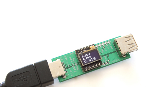
[Aleksejs Mirnijs] needed a tool to accurately measure the power consumption of his Raspberry Pi and Arduino projects, which is an important parameter for dimensioning adequate power supplies and battery packs. Since most SBC projects require a USB hub anyway, he designed a smart, WiFi-enabled 4-port USB hub that is also a power meter – his entry for this year’s Hackaday Prize.

[Aleksejs’s] design is based on the FE1.1s 4-port USB 2.0 hub controller, with two additional ports for charging. Each port features an LT6106 current sensor and a power MOSFET to individually switch devices on and off as required. An Atmega32L monitors the bus voltage and current draw, switches the ports and talks to an ESP8266 module for WiFi connectivity. The supercharged hub also features a display, which lets you read the measured current and power consumption at a glance.

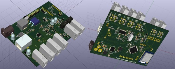
Unlike most cheap hubs out there, [Aleksejs’s] hub has a properly designed power path. If an external power supply is present, an onboard buck converter actively regulates the bus voltage while a power path controller safely disconnects the host’s power line. Although the first prototype is are already up and running, this project is still under heavy development. We’re curious to see the announced updates, which include a 2.2″ touchscreen and a 3D-printable enclosure.

Simple USB Power Meter

The USB interface is being increasingly used as a power supply and charging port for all kinds of devices, besides data transfer. A meter to measure the electrical parameters of devices connected to a USB socket or charger would be handy on any hacker workbench. The folks at [electro-labs] designed this simple USB power meter which does just that.

The device measures voltage and current and displays them, along with the calculated power, on the small 0.5″ OLED display. The circuit is built around an ATmega328. To keep the board size small, and reduce component count, the microcontroller is run off its internal 8MHz clock. A low-resistance shunt provides current sensing which is amplified by the LT6106 a high side current sense amplifier before being fed to the 10 bit analog port of the ATmega. A MCP1525 precision voltage reference provides 2.5V to the Analog reference pin of the microcontroller, resulting in a 2.44mV resolution. Voltage measurement is via a resistive divider that has a range of up to 6V. An Arduino sketch reads voltage and current data on the analog ports and displays measurements on the display. The measured data is averaged to filter out noise.

The OLED display has a SPI interface and requires the u8glib library. The project uses all SMD parts, but is fairly easy to assemble by hand and could be a nice starter project if you want to wet your feet on surface mount assembly techniques. It’s designed using SolaPCB EDA software, and the source files for schematic and board layout are available as a ZIP archive. Download the BoM and Arduino code and you have everything needed to build this nifty device.

Thanks to [Abdulgafur] for sending in this tip. And if you are looking for a more comprehensive solution, check the awesome Friedcircuits USB Tester which we reviewed earlier and is available in the Hackaday Store.