Top side of the VL670 breakout board, with two USB connectors and the VL670 chip in the center.

A Chip To Bridge The USB 2 – USB 3 Divide

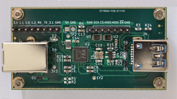
On Twitter, [whitequark] has  found and highlighted an intriguing design – a breakout board for the VL670, accompanied by an extensive yet very easy to digest write-up about its usefulness and inner workings. The VL670 is a chip that addresses a surprising problem – converting USB 2.0 signals into USB 3.0.

If you have a USB 2.0 device and a host with only USB 3.0 signals available, this chip is for you. It might be puzzling – why is this even needed? It’s about the little-known dark secret of USB3, that anyone can deduce if they ever have to deal with a 9-pin USB 3.0 connector where one of the three differential pairs doesn’t quite make contact.

When you see a blue “3.0” port, it’s actually USB 2 and USB 3 — two separate interfaces joined into a single connector. USB 3 uses two single-directional differential pairs, akin to PCI-E, whereas USB 2 uses a single bidirectional one, and the two interfaces on a blue connector operate basically independently of each other. There’s many implications to this that are counterintuitive if you simply take “USB 3.0” for “faster backwards-compatible USB”, and they have painful consequences.

For instance, USB 3 hub ICs have two separate hub entities inside – one for USB 3 and one for USB 2. Even if you have a USB 3 hub plugged into a USB 3 port, multiple USB 2 devices plugged into it still cannot break through the USB 2 uplink limit of 480 MBps. If you ever thought that a faster hub with a faster uplink would fix your USB 2 device speed problems – USB-IF engineers, apparently, thought differently; and you might have to find a workaround for your “many cheap SDRs and Pi 4 in a box” setup. Continue reading “A Chip To Bridge The USB 2 – USB 3 Divide”

Bitbanging Qualcomm Charge Controllers

With more and more manufacturers moving to USB-C, it seems as though the trusty USB port is getting more and more entrenched. Not that that’s a bad thing, either; having a universal standard like this is great for simplicity and interconnectability. However, if you’re still stuck with USB 2.0 ports on your now completely obsolete one-year-old phone, there’s still some hope that you can at least get rapid charging. [hugatry] was able to manipulate Qualcomm’s rapid charging protocol to enable it to work with any device.

Continue reading “Bitbanging Qualcomm Charge Controllers”

Hackaday Prize Entry: Smart USB Hub And IoT Power Meter

[Aleksejs Mirnijs] needed a tool to accurately measure the power consumption of his Raspberry Pi and Arduino projects, which is an important parameter for dimensioning adequate power supplies and battery packs. Since most SBC projects require a USB hub anyway, he designed a smart, WiFi-enabled 4-port USB hub that is also a power meter – his entry for this year’s Hackaday Prize.

[Aleksejs’s] design is based on the FE1.1s 4-port USB 2.0 hub controller, with two additional ports for charging. Each port features an LT6106 current sensor and a power MOSFET to individually switch devices on and off as required. An Atmega32L monitors the bus voltage and current draw, switches the ports and talks to an ESP8266 module for WiFi connectivity. The supercharged hub also features a display, which lets you read the measured current and power consumption at a glance.

Unlike most cheap hubs out there, [Aleksejs’s] hub has a properly designed power path. If an external power supply is present, an onboard buck converter actively regulates the bus voltage while a power path controller safely disconnects the host’s power line. Although the first prototype is are already up and running, this project is still under heavy development. We’re curious to see the announced updates, which include a 2.2″ touchscreen and a 3D-printable enclosure.

Getting Around The Raspi’s USB Host Current Limit

For being such a revolutionary device, there are still a few problems with the Raspberry Pi. For one, the USB host ports are only able to source 140 mA per port, while the USB ports on your desktop, laptop, and even tablet are able to send a full 500 mA per port.

The official ‘fix’ for this problem is to use a powered USB port for any device that requires more than 140 mA,  something that didn’t sit well with [Manis]. He came up with an easy fix , though, that only requires a few bits of wire and a soldering iron.

The USB ports on the Raspi are current limited to 140 mA by a pair of polyfuses. [Manis] bridged these fuses, effectively taking them out of the circuit with a short length of wire. This allowed him to use a USB hard drive (powered by USB, of course) with the Raspi.

There’s one small problem with sending that much current through the Raspi’s USB port. Sometimes, when the high-power USB device is powered on, the voltage will sag, resetting the SoC and rebooting the system. [Manis] did his homework and discovered USB 2.0-spec ports should use a 120 μF, low-ESR capacitor to prevent this. The Raspi comes stock with a 47 μF cap used for this purpose. Replacing this cap (C32) might be a good idea if you’re planning on using high-power devices with your Raspi.