Stealth Peephole Camera Watches Your Front Door

In this week’s links post we mentioned an over-powered DSLR peephole that purportedly cost $4000. So when we saw this tip regarding a relatively inexpensive digital peephole, we thought some of you might be a bit more interested.

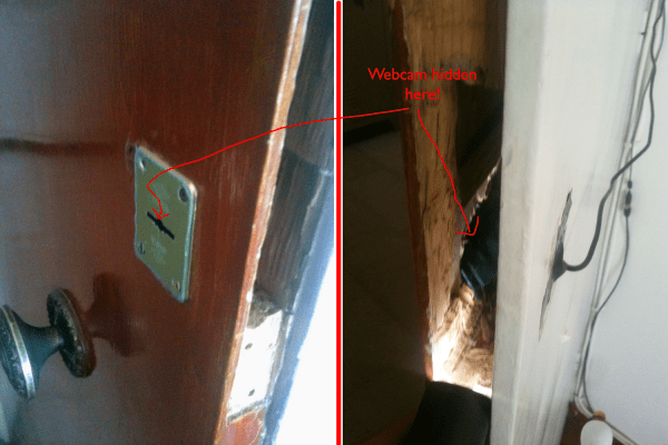
The hardware is quite simple; a decent webcam, a Raspberry Pi, and a powered USB hub. The camera gets stripped down to its PCB and hidden inside the door itself. Even if you see this from the inside it’s just a suspicious-looking wire which wouldn’t make most people think a camera was in use.

On the software side of things, [Alex] set up his Raspberry Pi as a 24/7 webcam server to stream the video online. Unlike using a cheap wireless CCTV camera, his video signals are secure. He then runs Motion, a free software motion detector to allow the camera to trigger events when someone comes sneaking by. It can be setup to send you a text, call you, play an alarm, take a picture, record a video… the list goes on. His blog has a full DIY guide if you want to replicate this system. We just hope you have a stronger door!

We covered a similar project back in 2011, but it had made use of real server instead of an inexpensive Raspberry Pi.

[Thanks Alex!]

Reverse Engineering A Wireless Protocol

logic

Like all good tinkerers, [Andrew] decided to figure out how his wireless security system worked. Yes, it’s an exercise in reverse engineering, and one of the best we’ve seen to date.

After breaking out the handheld spectrum analyzer and TV tuner SDR, [Andrew] cracked open a few devices and had a gander at the circuit boards. The keypad, PIR sensor, and base station all used a TI radio chip – the CC11xx series – that uses SPI to communicate with a microcontroller.

Attaching a logic analyzer directly to the radio chip and reading the bits directly, [Andrew] started getting some very good, if hard to understand data. From the security system specs, he knew it used a ’20-bit code’, but the packets he was reading off the SPI bus were 48 bits long. The part of this code was probably the system’s address, but how exactly does the system read its sensors?

The easiest way to figure this out was to toggle a few of the sensors and look at the data being transmitted. With a good bit of reasoning, [Andrew] figured out how the alarm system’s code worked. This theory was tested by connecting one of the radios up to an Arduino and having his suspicions confirmed.

While [Andrew]’s adventure in reverse engineering is only a benefit for people with this model of security system, it’s a wonderful insight into how to tear things apart and understand them.

Home Security Hardware Makes You The Monitoring Service

diy-home-security

[Nick] and [Simon] both have home security systems with a monitoring service who will call whenever an alarm is tripped. For [Simon] this ends up happening a lot and he wanted to change the circumstances that would trigger a call. Because of company policy the service is inflexible, so he and [Nick] went to work cutting them out of the loop. What they came up with is this custom electronics board which monitors the security system and calls or texts them accordingly.

They started with the self-monitoring alarm system design we looked at back in September. This led to the inclusion of the SIM900 GSM modem, which is a really cheap way to get your device connected to the cellular network. It also uses a DTMF touch tone decoder to emulate the phone line to keep the security system happy. [Simon] highlights several changes he made to the design, as well as the reasons for them. One idea he has for a possible revision is to do away with the MT8870 chip which handles the touch tones. He thinks it may be possible to use the SIM900’s DTMF features to do that work instead.

Bending A Home Security Control Panel To Your Will

Does your home have a security system but you don’t subscribe to the monitoring service to make it work? Rip that baby off of the wall and do something with it, or just build your own system around it. If you have a DSC PC1500RK control panel [CaitSith2] shows us how easy it is to control the buttons, LEDs, and buzzer. If you’ve got a different model this is still a good jumping off point to start your own reverse engineering.

There are only four connections that need to be made. [CaitSith2] is using an Arduino for the demonstration. He connected the red wire to voltage, the black wire to ground, the yellow wire (clock) to digital pin 3 and the green wire (data) to digital pin 2. A communication cycle starts by setting the data line high, then clocking out eight bits to capture keypresses. 16-bits are then clocked in to set the LEDs and drive the buzzer. This is shown in the video after the break as well as documented in his sample code. We’ve embedded the sketch after the break to preserve it in case the pastebin code goes missing in the future.

Continue reading “Bending A Home Security Control Panel To Your Will”