They May Be For Developing Countries, But We Want A Concrete Lathe

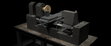
At the 2009 Ghana Maker Faire, [Pat Delany] met a young carpentry student that saved for three months to buy a cheap Chinese wood plane. He was confounded by this distribution of resources, so [Pat] created the Concrete Lathe project that aims to get useful machine tools out to where they’re needed most.

The idea for concrete machine tools came out of the US involvement in World War I. America had been staunchly isolationist before committing to the war, and production of arms did not match the needed output. A man named L.I. Yeomans came up with the idea of building concrete lathes to produce artillery shells for the war effort.

Of course, the concrete lathe project is a bit more peaceful in its intentions. The concrete lathe is meant to be a cheap machine tool for developing nations. Both the concrete lathe and the Multimachine are meant to be built cheaply using scrap materials, reduce training time for machinists, and create other machine tools in a Reprap-like biological distribution.

There’s a ton of documentation on the concrete lathe wiki like the bed instructions torn from the pages of Ikea instructions, and the thread follower. While they’re still a lot of work and testing to be done, giving some manufacturing capability to those who need it most is a pretty noble cause.

Thanks [Rob] for sending this one in.

Arduino Boards Control Cheap Clockworks Via Coil Injection

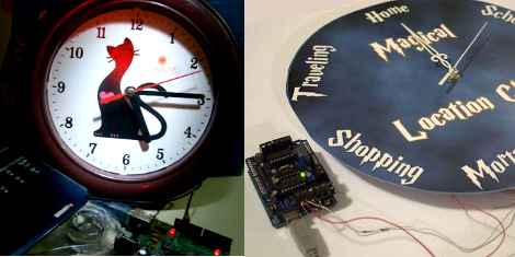
Here’s a couple of clocks that use Arduino boards to control inexpensive clockworks. The concept is quite simple, and perhaps best outlined by [Matt Mets’] article on the subject. As it turns out, these clockworks are driven by a coil, forming a device that is quite similar to a stepper motor. If you solder a wire onto each end of the electromagnetic coil and hook those to a microcontroller, you can alter the speed at which the clock ticks. Just drive one pin high and the other low, then reverse the polarity for the next tick.

The clock you see on the right (translated) is a store-bought cheapy. The Arduino barely visible at the bottom of the image is sending pulses once every second. But as you can see in the video after the break, holding down a button will fast-forward through time. [Sodanam] posted his code as well as pictures of the hardware hack itself.

To the left is a horse of a different color. It’s a clock modeled after the Weasley household clock from the Harry Potter books. The clockwork trick is the same, but the Arduino uses GPS data and NOAA weather information to set the status.

Continue reading “Arduino Boards Control Cheap Clockworks Via Coil Injection”

Turn Your Wireless Keyboard Into A MAME Controller!

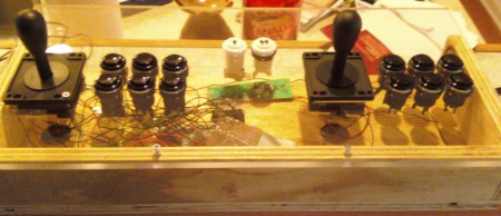
For those of you that have a wireless keyboard laying around, you might be tempted to turn it into something else, like a wireless MAME controller. For those not familiar with it, MAME stands for “Multiple Arcade Machine Emulator” and is generally used to run older arcade games on a computer.

Encoders are available for this purpose, however, intending to save some money, and having an unused wireless keyboard, I decided to try to make one myself.  As far as I know there are no wireless encoders available for this purpose, so that was part of the motivation for trying this.

In this post I go over my mechanical design for the cabinet as well as the electrical process of going from keyboard to MAME controller. I did eventually get the thing working, but if more than a couple buttons were pressed simultaneously, some presses were omitted. The conclusion I eventually came to was that it was better to use an encoder to control everything. Not wireless, but much more reliable. If I absolutely needed a wireless controller in the future, I would think modding an actual wireless controller (or two) in a similar manner would have worked better for my purposes.

DIY Breadboard Modules For Easy Prototyping

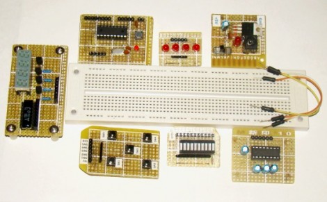
[Rajendra] got tired of building the same basic circuits time and again on the breadboard. He decided to build some simple, modular circuits on protoboard and make them easy to interface with the breadboard. As you can see, he ended up with seven modules that make prototyping faster and easier.

At first glance some might not seem all that beneficial. For instance, making a board for an 18-pin PIC microcontroller into a single-in-line form factor would seem like you’re actually wasting breadboard space when compared to the DIL package of the chip. But consider that the oscillator and its capacitors, reset button, and programming header are also on the breakout board and will not have to be built in place. There are also several I/O boards, one with five buttons, another with an LED bar graph, and a set of LEDs with a SIL resistor package on-board. These modules can be plugged into a breadboard and wired up with jumper wires, or connected directly to the same rows as the microcontroller module.

Two Dice, One 8-pin UC

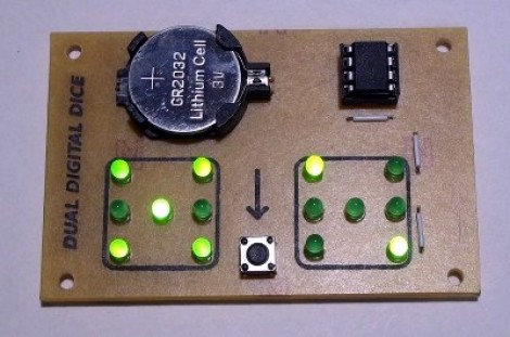
[Mike Shegedin] makes full use of an 8-pin microcontroller with this ATtiny13-based dice project. With a maximum of six I/O pins (that includes using the reset pin as I/O) he needed a couple of tricks in order to drive 14 LEDs and use a momentary push button for user input. We’re certainly familiar with the concepts here, but it still took quite a while to figure out what is going on with the schematic that [Mike] posted.

You’ve probably already guessed that he’s using Charlieplexing to drive more LEDs than he has pins. But when we started looking at the layout we thought he had drawn the schematic wrong, because there are six pairs of LEDs where the two diodes in each pair a not reverse biased, but hooked up in parallel. That, plus the fact that his battery is hooked up backwards. After several minutes of study the light bulb finally clicked on. Dice add pips (the dots on each side of a die) in pairs with the exception of the center pip. That means that you only need to control four total lines for each die (three pairs plus the center pip). There’s two ways to handle this, you could use four rows and two columns with traditional multiplexing, or you can reverse bias the two sets of LEDs for each die and use Charlieplexing. The former is a bit easier to program, the latter saves you one I/O pin and meant that [Mike] didn’t need to use the reset pin as I/O.

This is a clever addition to the collection of dice projects we’ve seen like the battery-less die, and the ATtiny2313 powered dice.

Building A Battery-powered Motion Alarm

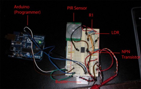
[Brad] was asked by his Sister to design a motion-based alarm that would help her catch her son sneaking out of the house at night. Obviously this didn’t need to be a long-term installation so he decided to throw something together that is only active at night and can be battery-powered. What he came up with is a light-sensitive motion sensor that uses very little power.

He knew that an Arduino would be overkill, and decided to try his hand at using the Arduino to develop code for an ATtiny85. It has an external interrupt pin connected to the output of the PIR module, which triggers action when motion is detected. The first thing it does is to check the photoresistor via the ADC. If light levels are low enough, the buzzer will be sounded. [Brad] measured the current consumption of his circuit and was not happy to find it draws about 2.5 mA at idle. He spent some time teaching himself about the sleep functions of the AVR chips and was able reduce that to about 500-600 uA when in sleep mode. Now all he has to do is find a nice place behind the house to mount the alarm and there’ll be no more sneaking around at night.

If you’re trying to keep a tight leash on your own kids you could always make them punch the time clock.

Sustainability Hack: Wind Turbine Battery Charger

Hit your parts bin and set aside an afternoon to build a wind turbine that recharges batteries. You can see two AA batteries hanging off the side of this small generator. You only need a few parts to make this happen, and chances are you have them sitting in your junk bin already.

The generator itself is a small stepper motor which can be pulled from a floppy disk drive or a scanner. The blade is cut from a single piece of 3.5″ (90mm) PVC pipe, with another piece of smaller-diameter pipe serving as the body of the turbine. The tail-fin makes sure it’s always pointing into the wind and was made from some plywood. As the blade spins, a current is induced on the control pins of the stepper motor. By building a pair of bridge rectifiers and using an RC filter you’ll get the most out of the generated current.

This turbine can charge a pair of NiCad batteries in about 10 hours, but it might be worth developing some smart circuitry to manage charging. If it were able to choose between a dedicated storage battery and the on-board battery holder you could put all of the wind energy to good use.

[Thanks Michael]