Visualizing A Nanosecond

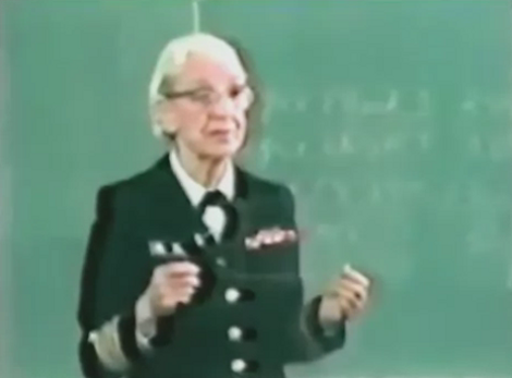
We’re so glad to have run across this video where [Rear Admiral Grace Hopper] explains how to visualize a nanosecond. Now we had never heard of [Grace Hopper] before, but once you watch the clip (also embedded after the break) you’ll want to know who this person is. We work with divisions of seconds all the time when developing with microcontrollers. But those concepts are so abstract we never had a need to think about them as a physical distance. After all they’re a measure of time, right?

You can’t make it out, but she’s holding a length of wire between her hands. It is 11.8 inches long and represents how far electricity can travel in one nanosecond (one billionth of one second). She goes on to explain that this is a calculation of the distance which light can travel in one nanosecond, then really hits the concept home when she uses it to explain latency in satellite communications. For us, the waste of not putting a chip into sleep mode when it’s just stuck in the loop waiting for an interrupt is where we made the connection.

So back to the woman herself. We think you’ll really enjoy reading through her Wikipedia biography page. [Grace] was a computer science pioneer. She is credited with writing the very first computer compiler. She postulated and articulated the concepts that led to the development of COBOL, and popularized the term ‘debugging’. In short, she is one of the giants whose shoulders we all stand upon.

Continue reading “Visualizing A Nanosecond”

Make Any Photo 3D Using The Gimp

Put your face close to the screen and cross your eyes until the two images above become one. You may need to adjust the tilt of your chin to make it happen, but when they come together you’ll see [John Lennon] pop out in 3D. This was made using a 3D rendering script for The Gimp.

The process is not entirely automatic, but it won’t take too long to mask off the outlines for different depth layers. The script makes three different layers from the image. One of them is a color-coded depth map that uses a custom color palatte to choose distance for each item. If you paint the background dark blue it will be processed at the furthest distance from the viewer’s cross-eyed perspective, yellow is the nearest.

[Don] mentions a parallel output and a cross-eyed output in his write up. We understand the cross-eyed version, but are just guessing that the parallel version would be used in a stereoscopic viewer that puts a partition between the two images so that each eye sees a different frame. You know, like a View-Master.

DIY Quadcopter For Around $200

We think [FlorianH] did a bang-up job of prototyping his Minima Quadcopter on the cheap. The total bill comes in right around $200 and we’re very happy with the quality of parts as well as the results.

Here you can see the top of the double-sided board which he etched to host all of the components. At each corner there is a power MOSFET which drives the motor. At first glance we thought that the Xbee module was acting as the radio control and processer as well. But on the underside you’ll find an ATmega32 which is responsible for reading the Gyroscope sensor and Accelerometer, processing these signals and driving each MOSFET via PWM lines to provide stability.

You can see some flight tests after the break. [FlorianH] mentions that there is some oscillation in the feedback loop when both the gyro and accelerometer are used. But cut the accelerometer out of the equation and the platform is rock-solid.

This build uses carbon tubes to mount the motors, which we think will be a little more robust than the all-PCB designs are.

Continue reading “DIY Quadcopter For Around $200”

Light Painting With A String Plotter

[Matt Bell] sends a shout-out to Hackaday by creating a light-painting of our logo with his string plotter. He starts off by setting up a pair of stepper motors which each have a spool to wind and unwind a string. The plotter is made by suspending a stylus between these two strings. In this case, he’s using a wireless LED board (seen above) built from the remote control receiver/transmitter from a toy car. The link above is part of a Flickr set from which you can get the whole story by reading the captions of each image.

After the break we’ve embedded a clip of an in-progress light painting. You can see there’s some oscillation of the LED unit that makes it a bit less precise than the CNC light painter we saw a couple of weeks ago. It seems like string plotters usually don’t have this issue if the stylus has something to help stabilize it. We wonder if a piece of acrylic would help get rid of the shakes? Continue reading “Light Painting With A String Plotter”

Anodize Titanium At Home

We don’t really have any titanium lying around, it’s not exactly a cheap material. But this hack that shows you how to anodize titanium in your home laboratory (or kitchen for that matter) and it might help the metal make its way into a future project. It seems the process is not overly difficult or dangerous and it’s possible to achieve a lot of different colors in the finish.

In the image above [PinkFlute] is using Coke Zero, a sugar-free soda, as the chemical agent in the process. The alligator clip attached to the utensil is providing the positive voltage and the yellow wire dipped in the drink is negative. Finish color is determined by the voltage supplied. You can choose various shades of green, purple, yellow, and blue based on a voltage range of about 100V to 20V.

This is one of two anodizing methods shown. the other uses a foam brush dipped in soda with the negative lead clamped onto it. You just brush in the electrified substance to alter the camping spork’s finish.

[via Reddit]

Adding Footwell And Glove Box Lights To Your Ride

[KonaStar] shows us that adding some light to you car interior isn’t very hard. It’s just a matter finding some unused space and routing the cables so that they’re out of sight. Here he’s added LED lighting to the footwells and glove box of his car.

He managed to find some depressions in the molded dashboard of the car which were just the right size for a small four-lead LED. He drilled holes for those leads, and soldered some protoboard to them on the inside of the dash. This way there’s nothing unfinished to catch your eye, and the protoboard provides an area to host the resistor and interconnect.

There are switches in the glove boxes that turn the lights off when closed. These work for the footwells too. In addition, the LED lighting harness is wired to the parking lights so they will not come on when the car’s lights are off. Because he started with a lighting harness intended to add ambient light to a vehicle, the system responds to the doors being opened as well.

It’s a nice addition if you don’t mind pulling out several pieces of your interior during the install. We’re more comfortable with something along the lines of this turn signal hack.

DIY Intervalometer Uses A Great Looking Enclosure

That finished look for your project is all about the enclosure you find to host it. We think [Punge] really did a great job with the case for this DIY intervalometer. The build section of the project page links to the company that makes the enclosures. They’re meant to host round PCBs with several options for button configuration. Combine this with enough space for a coin cell and you’ve got a great looking custom device.

The intervalometer itself is much like others we’ve seen. It uses an audio-jack connector to control the camera. You have the option of using a three or four contact version depending on what your camera supports. The PIC 12F683 uses an optocoupler with a built-in transistor to do the switching. A single button seen at nine o’clock on the board above is all it takes to start the device off. Press and hold once to wake it up, then wait for your desired interval and press the button again to start the timed shots.

You’ll notice that there is no programming head in this design. A separate board was etched to attach the PicKit, with the surface mount chip just held in place during programming.