Retrotechtacular: Upgrading Train Signaling Before The Information Age

retrotechtacular-british-railway-signaling

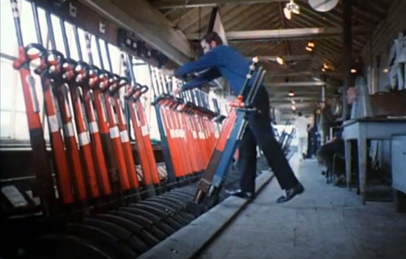
What’s surprising about the subject of this week’s Retrotechtacular is that the subject is not from that long ago. But looking at the way in which the work was done makes it feel so far in the past. In 1974 the British Railways Board set out to modernize and interconnect the signaling system. What you see above is one of hundreds of old signal control houses slated to be replaced by an interconnected system.

These days we take this sort of thing for granted. But from the start of the project it’s clear how the technology available at the time limited the efficiency of the development process. We’re not talking about all of the electro-mechanical parts shown during the manufacturing part of the video. Nope, right off the bat the volumes of large-format paper schematics and logic diagrams seem daunting. Rooms full of engineers with stacks of bound planning documents feel alien to us since these days even having to print out a boarding pass seems antiquated.

With fantastic half-hour videos like this one available who needs television? We’d recommend adding this to your watch list so you can properly enjoy it. They show off everything; manufacturing the cables, stringing them between the signal towers, assembling the control panels, testing, and much more.

Continue reading “Retrotechtacular: Upgrading Train Signaling Before The Information Age”

Upstagram: A Flying Raspberry Pi

Upstagram Pre-flight

This tiny paper house, modeled after the one in Disney’s UP, contains a Raspberry Pi, battery pack, camera, and 3G stick. The Upstagram, built by the folks at HackerLoop, took to the skies of Paris to snap and share photos on Instagram.

We’ve seen Raspberry Pis in flight before, but this build pulls it off using simple party balloons. It took around 80 balloons to get the house to a height of 300 feet. A kite string was used to tether the device and control its flight.

This hack also required some reverse engineering of Instagram. Since the photo sharing service only allows the official Android and iOS apps to upload, they had to use a reverse engineered Instagram client. This allows the unsupported Raspberry Pi to interact with the service, snapping pictures periodically and sharing them on the device’s stream.

After the break, check out a quick video overview of the project.

Continue reading “Upstagram: A Flying Raspberry Pi”

Wireless Keurig Hack!

coffeemaker

[Kolumkilli] loves his Keurig coffee maker, as it makes him an excellent cup of coffee, but he doesn’t like waiting for it to brew. So he set out to make it wirelessly controlled via his computer… with the press of a button, he can have his coffee ready and waiting for him when he gets up.

After carefully dismantling his Keurig, he set to locating the main buttons on the PCB, and proceeded to wire in relays in parallel to the ones he wanted to control. Throw in a Moteino and add the notification LEDs as inputs as well and now he can control and monitor almost all the coffee maker’s functions via a web browser at his desk. Now if only he could remember to put a new coffee cup in…

There’s a great writeup on the forum post, so if you want to see a more detailed build log, check it out! And if you’re looking to add even more functionality to your Keurig, why not run a waterline to it?

[Thanks Felix!]

Keep Your SD Cards Data Safe With The SD Locker

sdlocker_1

[Karl Lunt] has come up with a simple circuit for protecting data you have stored on SD cards. As is relatively well-known, the little lock switch on the side of most SD cards really doesn’t do anything more than the switch on floppies or the tabs on VHS or cassette decks. It’s up to the reader/writer to check the status of the tab and decide if it should write to the card or not. Not a very safe system. However, it’s not the only write protection system built into SD and SDHC cards. As part of the standard, cards have three protection methods: A TMP_WRITE_PROTECT bit, a PERM_WRITE_PROTECT bit, and a PWD register.

The PERM_WRITE_PROTECT bit permanently write protects the card. The bit can not be reset, so you should be really sure you want to keep the data on the card forever. The PWD register is a password register. The card will not allow any access (read or write) unless a password is provided. The TMP_WRITE_PROTECT bit is a temporary write protect. This is the bit that [Karl] is working with. When TMP_WRITE_PROTECT is set, the card can be read but not written. Note that there is no true protection here, as anyone can modify the bit. However, this should stop grandma from accidentally deleting your wedding pictures.

[Karl’s] device is very simple. A card is inserted into an Altoids tin enclosure. One button locks the card, another unlocks it. Three LEDs return status – power, card locked, and card unlocked. Under the hood, he’s using an Atmel ATmega328 to set and clear the TMP_WRITE_PROTECT bits. Power is provided by two AA batteries, and regulated with a Pololu 3.3v boost regulator. [Karl] has also included a serial port for control and debug information. We think this is a great hack, however one thing we’re not sure of is how or if these features are implemented in all cards. We’re relatively sure the name brand cards stick to the SD/SDHC spec sheet, but what about all the knockoff and no name brands from overseas?

Reverse Engineering The Sony Ericsson Vivaz High Resolution 640 X 360 Cellphone LCD

In our opinion, reverse engineering may be one of the best ways to tease your brain. [Andy] just did that by reverse engineering the Sony Ericsson Vivaz high resolution LCD (cached copy here). In his (very) nicely written article, [Andy] explains all the steps that led him to the result shown in the picture above. He started by finding the repair manual of the Vivaz, to discover that the display could be interfaced with 8080 type parallel signals. That meant that he could use a standard microcontroller without high speed buses to interface with it, in this case the STM32F4. Next in his adventure, [Andy] ordered the appropriate connector and took a more educated guess for the onboard microcontroller. A long Google search brought up the R61523 from Renesas. So he designed his breakout board, got it produced and a few hours later a nice picture was being shown on the LCD. He even took the time to compare the original display with the clone he found on the webs, and modified his graphics library to support this display.

HackPrinceton: Piano Stairs!

princeton piano

It was Hack.Princeton this weekend and [Bonnie] and [Erica] threw together this great interactive portable piano!

The setup is very simple using six LED flashlights, and six photoresistors. An Arduino Uno reads in the values from the photoresistors and parses them to a nearby Raspberry Pi which then creates the sounds. The system even automatically calibrates itself when turned on, adjusting to the ambient light conditions. They made the project for the Hackathon and after a short scare of having to move it to another staircase for the demo, they took home 2nd place in the hardware category!

Stick around after the break to see it in action — this would make a great school project to get kids interested in hacking!

Continue reading “HackPrinceton: Piano Stairs!”

Reverse Engineering The Z80’s 16-bit Increment/Decrement Circuit

z80

Increment and decrement. They sound like simple functions. But even the simplest functions can get quite complex in a microprocessor design. Ken Shirriff has written up a great blog post about his reverse engineering of the Z80’s 16-bit increment/decrement circuit. The Zilog Z80 was one of the most popular microprocessors of the 70’s and 80’s. It was used in many classic computers such as the Osborne 1. These machines would often use the Z80 to run the popular CP/M operating system.

The increment/decrement circuit is responsible for updating the program counter register during normal (non branch) operations. The increment/decrement circuit also handles the stack pointer register during stack operations, as well as several other functions. One might wonder why a separate adder would be used when the microprocessor has a big ALU available to it. The answer is twofold. First the ALU is already in use handling user math operations. Secondly the increment/decrement circuit has to be fast. A generic ALU just won’t be fast enough.

One classic adding circuit is a Ripple Carry Adder. Ripple Carry Adders get the job done, but they are slow. Note slow is measured in nanoseconds here – there are no clocks involved in the circuit. The whole thing becomes a classic combinational logic optimization problem. Each layer of logic adds a gate delay to the circuit. As the carry has to ripple through all 16 bits, there are 16 gate delays before the final result is available at the outputs. Delays like these are what limits the maximum clock speed for a given circuit.

The Z80 uses some tricks in its increment/decrement circuit. The first is Carry-lookahead. A carry-lookahead circuit will calculate the carry values directly from the inputs. This reduces the gate delays significantly, but it requires more real estate on the die. A second trick is the carry-skip circuit. Carry-skip calculates the result for groups of bits rather than each bit individually. Again, it will reduce gate delays, at the cost of real estate. The actual Z80 implementation uses a mix of both circuits. Several other “helper” circuits are also used. Surprisingly the Z80 has specific logic just to check for 1 (0x0001) on the internal address bus. This circuit is used during memory move loops to inform other parts of the chip that a loop is about to complete.