Peltier Joule Thief Power Supply

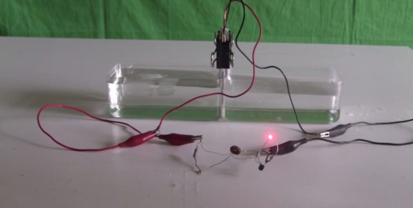
[Steven] manages to power an LED for 15 minutes using hot and cold water as a battery. He does this using the thermoelectric effect also known as the Seebeck effect, Peltier effect or Thomson effect. This isn’t particularly new; in fact there are commercial products that you can use to charge a cell phone using a small campfire or internal burner that works on the same principle.

What is interesting about [Steven’s] device is that he uses a salvaged Peltier device not meant for generating electricity, coupled with a home built joule thief circuit. In the video he describes how the joule thief functions and powers the LED using the small voltage generated by the Peltier device. The energy for the thermoelectric effect is conducted from a hot water bath through aluminum plates, through the positive and negative sides of the Peltier device, through more aluminum plates and finally into a cold water bath. As the heat energy transfers through the Peltier device a small electric current is generated and flows in two small wires coming out the side of the device.  The energy generated by the Peltier device is stored in the joule thief and periodically dumped at a voltage high enough to forward bias the LED “on” for a brief moment. Technically the LED is flashing but at a frequency too high for our eyes to see. As the hot water bath cools, the LED goes from very bright, to dim, to off in about 15 minutes.

Not a very practical power supply but still quite the parlor trick. He wraps up the tutorial specifying that a TEG thermoelectric generator would be a much better choice for generating power and can handle much higher temperatures. You can watch the video after the break.

Continue reading “Peltier Joule Thief Power Supply”

Sailing With An Autopilot

sailboat

After seeing an autopilot for a kayak a few days ago, [Mike] thought he should send in his version of a water-borne autopilot. Compared to something that fits in a one-man kayak, [Mike]’s creation is a monstrous device, able to keep a largeish sailboat on a constant heading.

To keep track of the ship’s bearing, [Mike] is using a very cool digital compass that uses LEDs to keep a steady heading. Also included is an amazingly professional and very expensive 6 axis IMU. To actually steer the ship, [Mike] is using a linear actuator attached to the tiller powered by a huge 60 Amp motor controller. The actuator only draws about 750 mA, but if [Mike] ever needs an autopilot for a container ship or super tanker, the power is right there.

For control, [Mike] ended up using an Arduino, 16-button keypad, and an LCD display. With this, he can put his autopilot into idle, calibration, and run modes, as well as changing the ship’s heading by 1, 10, and 100 degrees port or starboard.

From a day of sailing, [Mike] can safely say his autopilot works very well. It’s able to keep a constant heading going downwind, and even has enough smarts to tack upwind.

Videos below.

Continue reading “Sailing With An Autopilot”

A Simple Servo Hack For An Iron Man Helmet

iron man helmet

[James] makes some seriously awesome Iron Man props. In one of his latest helmet builds, he came across a handy hack to lock the faceplate servo in place.

You see, as awesome as it is walking around like Iron Man all day, you’re going to want to keep your faceplate up for extended periods of time. Simply holding the servo in place electronically is a waste of power, and results in the annoying sound of a servo under strain. On the other hand, cutting power to it will keep it in place momentarily — but it will also start to close under the force of gravity.

The solution is actually quite simple, by reprogramming the Picaxe-08M microcontroller, the board now shorts the motor terminals to hold it in place. This is called magnetic motor braking, and it works by creating a closed loop that makes it much harder to induce a current under load. We once added this feature to a motorized push-scooter — it’d stop on a dime, although you wouldn’t…

Stick around after the break to see an extremely in depth video on how he setup the entire system.

Continue reading “A Simple Servo Hack For An Iron Man Helmet”

Printing Printed Circuit Boards

circuit

We really respect the old timers out there and their amazing ways of crafting PCBs; they used black tape on clear acetate sheets to create single layers of PCBs with a photoetching process. Now creating a PCB is a simple matter of opening up a CAD package, but like the old timers we’re still dealing with nasty chemicals or long shipping times from China.

The EX¹, a new robot on Kickstarter – hopes to change that. They’ve created a PCB fabrication process that’s as simple as printing something with an inkjet printer. Just put in a piece of substrate – anything from Kapton to acrylic to fabric – and in a few minutes you have a single-sided PCB in your hands.

The printer dispenses two chemicals, silver nitrate and ascorbic acid, that react and produce traces and pads for the circuit. Right now, the EX¹ is limited to single-side boards, but experiments on creating multi layer boards are ongoing.

In any event, we’re really impressed with how simple the EX¹ setup actually is. Inkjet is a mature, well understood technology with more than enough resolution for simple homebrew circuits, and the AgNO3 + Vitamin C formula could easily be adapted to an inkjet printer modification.

Building A Better Serial Camera

If your next project does anything with cameras or machine vision, you’ll probably be looking at something like a USB webcam attached to an ARM board or a netbook. Sometimes, though, that setup blows will blow your budget – power or otherwise – out of the water. For small projects, you’re limited to small, serial-accessible cameras, and in that domain you really don’t have a lot of choices.

[Ibrahim] realized the cheapest serial cameras are about $35, and with basic image processing that cost skyrockets up to about $100. He set out to build his own alternative, and ended up with an awesome serial camera module that should only cost about $15 in quantity.

The module is built around an STM32F4 microcontroller running at 168 MHz. This micro has a DCMI port to which a OV9650 camera is attached. The resolution ends up being 1280×1024, far better than other serial cameras.

Already [Ibrahim] has the hardware working and a few demo apps. He has a real time color tracking demo (video below) up and running and a machine vision repo for his tiny camera. Now if we could only get a few of these boards on Tindie.

Continue reading “Building A Better Serial Camera”

Retrotechtacular: Upgrading Train Signaling Before The Information Age

retrotechtacular-british-railway-signaling

What’s surprising about the subject of this week’s Retrotechtacular is that the subject is not from that long ago. But looking at the way in which the work was done makes it feel so far in the past. In 1974 the British Railways Board set out to modernize and interconnect the signaling system. What you see above is one of hundreds of old signal control houses slated to be replaced by an interconnected system.

These days we take this sort of thing for granted. But from the start of the project it’s clear how the technology available at the time limited the efficiency of the development process. We’re not talking about all of the electro-mechanical parts shown during the manufacturing part of the video. Nope, right off the bat the volumes of large-format paper schematics and logic diagrams seem daunting. Rooms full of engineers with stacks of bound planning documents feel alien to us since these days even having to print out a boarding pass seems antiquated.

With fantastic half-hour videos like this one available who needs television? We’d recommend adding this to your watch list so you can properly enjoy it. They show off everything; manufacturing the cables, stringing them between the signal towers, assembling the control panels, testing, and much more.

Continue reading “Retrotechtacular: Upgrading Train Signaling Before The Information Age”

Upstagram: A Flying Raspberry Pi

Upstagram Pre-flight

This tiny paper house, modeled after the one in Disney’s UP, contains a Raspberry Pi, battery pack, camera, and 3G stick. The Upstagram, built by the folks at HackerLoop, took to the skies of Paris to snap and share photos on Instagram.

We’ve seen Raspberry Pis in flight before, but this build pulls it off using simple party balloons. It took around 80 balloons to get the house to a height of 300 feet. A kite string was used to tether the device and control its flight.

This hack also required some reverse engineering of Instagram. Since the photo sharing service only allows the official Android and iOS apps to upload, they had to use a reverse engineered Instagram client. This allows the unsupported Raspberry Pi to interact with the service, snapping pictures periodically and sharing them on the device’s stream.

After the break, check out a quick video overview of the project.

Continue reading “Upstagram: A Flying Raspberry Pi”