Sometimes it’s fun to take a step back from the normal electronics themes and feature a marvelous engineering project. This week’s Retrotechtacular looks at a pair of videos reporting on the progress of the Bay Area Rapid Transit system. Anyone who’s visited San Francisco will be familiar with the BART system of trains that serve the region. Let’s take a look at what went into building the system almost half a century ago.
Year: 2013
5 Digit Security Code Activated Relay Using Mostly Discrete Circuitry
Let’s rollback the hobby electronics calendar a few decades with [myvideoisonutube’s] alarm activation control circuit using a matrix style phone keypad. The circuit is quite old using CMOS 4081 with 4 ‘AND’ gates to hardwire the access code. [myvideoisonutube] references [Ron’s] “Enhanced 5-Digit Alarm Keypad” schematic for this build changing the recommend keypad with a more common matrix style keypad found in touch pad phones. These types of matrix keypads wouldn’t work outright for the input so he cut some traces and added hookup wires to transform it into a keypad with common terminals and separately connected keys. We love seeing such hacked donor hardware even when it requires extensive modifications. [Ron’s] source circuit included a simple enough to build tactical button keypad if you can’t find a suitable donor phone.
Learning how to use mostly discrete components instead of a microcontroller would be the core objective to build this circuit outside of needing a key-code access point or other secure 12 V relay activated device. Such a device would be quite secure requiring a 4 digit “on” code and 5 digits for “off”. You couldn’t just pull off the keypad and hotwire or short something to gain access either. The 4 digit on “feature” does knock the security down quite a lot. However, all keys not in the access code are connected to the same point so you could increase your security by using a pad with more keys.
On [Ron’s] site you will find a detailed construction guide including top and bottom view for placement of all the components on veroboard. Join us after the break to watch [myvideoisonutube] demo his version.
Continue reading “5 Digit Security Code Activated Relay Using Mostly Discrete Circuitry”
Android Controlled RGB Lights

Here’s a handy hack for an Android controlled, Arduino driven, RGB light setup.
[Kerimil] recently wrote up this project on the Arduino.cc, and is sharing all of the source code and plans. While many of our seasoned Arduino-lovers can easily throw together the code for an RGB LED circuit in their sleep, [Kerimil] also threw in the Android app, and the source file to be modified in App Inventor, an Android app development program originally released by Google, but now maintained by MIT.
We’ve seen many commercial versions of this product, but it’s nice to see one that can be easily hacked to our liking. Next up is writing an app to use the phone’s camera to identify colors and reproduce them with the LED! While you’re at it, why not mix it with an easy to build infinity mirror!
To see the board and app in action, check out the video after the break.
Flickering Pumpkin Lanterns

Halloween is coming and [Paulo] decided to make some flickering jack-o-lanterns by hijacking the flickering circuit of a cheap LED tea light to drive a much more powerful light!
He has tons of old 12V incandescent bulbs collecting dust, so he decided to make use of them for some holiday fun. He wondered if he could steal the circuit from the flickering LED tea lights and use them to drive the incandescents. Upon taking the LED tea candle apart, he discovered there was no circuit, as it was in fact embedded in the LED itself! Not to worry though, he simply integrated the flickering LED into his circuit! Coupling a capacitor with the LED, he used a transistor amplifier to take the signal, and then finally boosted it using a MOSFET to drive the light bulbs. He then powered the entire thing using an old laptop power brick. Nice one [Paulo]!
Do you have any cool Halloween hacks? Don’t forget to send them in to the tip line! For other pumpkin fun, check out last year’s Pumpkin Tetris!
GuruBrew’s 15 Minute Windows 8 Survival Guide
One thing very common to all of us is our reliance on operating systems in our hobby life. If that OS is Windows then you could be in for quite a shakeup with Windows 8. Many readers are Linux or Apple users and couldn’t care less if Microsoft is releasing an entire paradigm shift in desktop navigation. However, you just might find yourself facing this new OS and you’ll look like you’re on training wheels if you don’t get acquainted now, and considering the number of computers being released with Windows 8 its inevitable that day will come soon.
So if you haven’t been behind the wheel of Windows 8 then checkout [Steve’s] Windows 8 Survival Guide from the Guru Brew Tech Show. This is an excellent overview of the new touch screen navigation methods you’ll find in the Windows 8 desktop including hotspots, charms and tiles to name just a few. You’ll also learn tips to get around with a mouse and keyboard. It’s not a complete tutorial on using Windows 8 but you’ll at least know how to navigate, search for apps, work with multiple apps and find tools like task manager, control panel, file explorer as well as your familiar desktop.
Follow the break to watch the short survival guide video.
Continue reading “GuruBrew’s 15 Minute Windows 8 Survival Guide”
An Atmega328-based Radioteletype XY Scope Display
[Jack] tipped us about a Crossed Bananas Display (CBD) he just designed. A CBD is a tuning aid for frequency-shift keyed (FSK) modes and is basically an oscilloscope in X-Y mode. At one time, radioteletype operators used binary FSK to transmit text over radio waves. In this scheme, the “1” is called the mark frequency and the “0” is called the space frequency. If both frequencies were perfectly tuned (correct phase) the resulting display would look like the one shown above, explaining the origin of the “crossed banana” name.
The build is based on an ATmega328 and a 1.8″ ST7735R display which has a 128×160 resolution. The MC33204PG operational amplifier is used in conjunction with a potentiometer to scale the input in the microcontroller ADC’s range. Another potentiometer sets the refresh rate of the graph. The whole project is enclosed in a painted cast-aluminium bud box and all the sources for this project can be found here.
DIY Soda Can Battery

It may not be particularly useful to create some makeshift batteries out of soda and soda cans, but it’s a good introduction to electrodes and electrolytes as well as a welcomed break from lemons and potatoes. The gang at [Go-Repairs] lopped off the can’s lid and temporarily set the soda aside, then took steel wool to the interior of the can to remove the protective plastic coating. The process can be accelerated by grabbing your drill and cramming the steel wool onto the end of a spade bit, although pressing too hard might rip through the can.
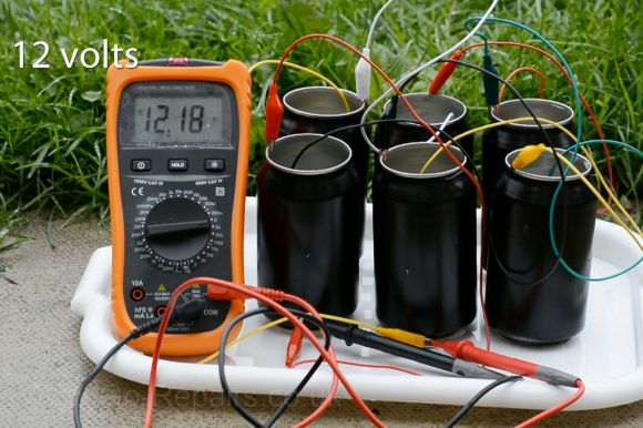
With the soda poured back in, you can eek out some voltage by clipping one lead to the can and another to a copper coin that’s dunked into the soda. Stringing along additional cans in series can scale up the juice, but you’ll need a whole six pack before you can get an LED working—and only just. The instructions suggest swapping out the soda for a different electrolyte: drain cleaner, which can pump out an impressive 12 volts from a six pack series. You’ll want to be careful, however, as it’s likely to eat through the can and is one lid away from being dangerous.
Stick around for a quick video after the break, and if you prefer the Instructables format, the [Go-Repairs] folks have kindly reproduced the instructions there.


