Internet-Connected TI-84

Just before the days where every high school student had a cell phone, everyone in class had a TI graphing calculator. In some ways this was better than a cell phone: If you wanted to play BlockDude instead of doing trig identities, this was much more discrete. The only downside is that the TI calculators can’t easily communicate to each other like cell phones can. [Christopher] has solved this problem with his latest project which provides Wi-Fi functionality to a TI graphing calculator, and has much greater aspirations than helping teenagers waste time in pre-calculus classes.

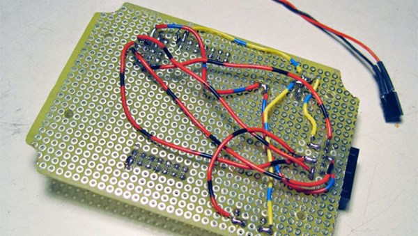
The boards are based around a Spark Core Wi-Fi development board which is (appropriately) built around a TI CC3000 chip and a STM32F103 microcontroller. The goal of the project is to connect the calculators directly to the Global CALCnet network without needing a separate computer as a go-between. These boards made it easy to get the original Arduino-based code modified and running on the new hardware.

After a TI-BASIC program is loaded on the graphing calculator, it is able to input the credentials for the LAN and access the internet where all kinds of great calculator resources are available through the Global CALCnet. This is a great project to make the math workhorse of the classroom even more useful to students. Or, if you’re bored with trig identities again, you can also run a port of DOOM.

CNC Router Converted to 3D Printer

CNC Router Converted To 3D Printer

3D Printers have come down significantly in price over the past few years. Nowadays it is even possible to get a 3D printer kit for between $200-300. It’s arguable how well these inexpensive printers perform. [Jon] wanted a printer capable of quality prints without breaking the bank. After researching the different RepRap types that are available he concluded he really wasn’t up for a full machine build. He had previously built a CNC Router and decided it was best to add a hot end and extruder to the already built 3 axis frame.

The CNC Router frame is made from aluminum, is very rigid and has a 2′ by 2′ cutting area. All axes glide smoothly on THK linear bearings and are powered by NEMA 23 motors driven by Gecko 540 stepper drivers. The router was removed from the machine but the mounting bracket was left on. The bracket was then modified to hold the extruder and hot end. With 3D Printers there is typically a control board specifically designed for the task with dedicated outputs to control the temperature of the hot end. Since [Jon] already had the electronics set up for the router, he didn’t need a specialized 3D Printer control board. What he does need is a way to control the temperature of the hot end and he did that by using a stand-alone PID. The PID is set manually and provides no feedback to the computer or control board.

Huge Whistle
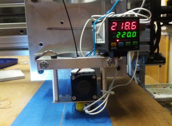
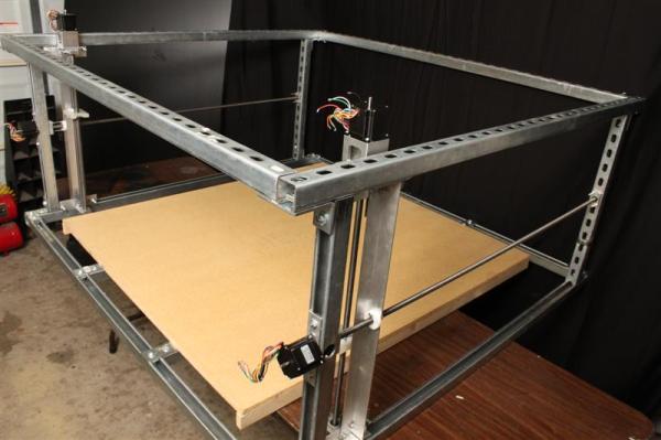
[Jon] used liked Mach3 for controlling his CNC Router so he stuck with it for printing. He’s tried a few slicers but it seems Slic3r works the best for his setup. Once the g-code is generated it is run though Mach3 to control the machine. [Jon] admits that he has a way to go with tweaking the settings and that the print speed is slower than most print-only machines due to the mass of the frame’s gantry and carriage. Even so, his huge whistle print looks pretty darn good. Check it out in the video after the break…

Continue reading “CNC Router Converted To 3D Printer”

Dusty Junk-bin Downconverter Receives FM On An AM Radio

This amateur radio hack is not for the faint of heart! With only three transistors (and a drawer-full of passive parts), [Peter Parker, vk3ye] is able to use a broken-looking AM car radio to receive FM radio signals (YouTube link) on 2 meters, an entirely different band.

There are two things going on here. First, a home-made frequency downconverter shifts the 147 MHz signal down to the 1 MHz neighborhood where the AM radio can deal with it. Then, the AM radio is tuned just slightly off the right frequency and the FM signal is slope detected.

The downconverter consists of a local tuned oscillator and a mixer. The local oscillator generates an approximate 146 MHz signal from an 18 MHz crystal, accounting for two of the three transistors. Then this 146 MHz signal and the approximately 147 MHz signal that he wants to listen to are multiplied together (mixed) using the third transistor.

If you’re not up on your radio theory, a frequency mixer takes in two signals at different frequencies and produces an output signal that has various sums and differences of the two input signals in it. It’s this 147 MHz – 146 MHz = 1 MHz FM signal, right in the middle of the AM radio band’s frequency range, that’s passed on to the AM radio.

Next, the AM radio slope detects the frequency-modulated (FM) signal as if it were amplitude modulated (AM). This works as follows: FM radio encodes audio as changes in frequency, while AM radios encode the audio signal in the amplitude, or volume, of the radio signal. Instead of tracking the changing frequency as an FM radio would, slope detectors stick on a single frequency that’s tuned just slightly off from the FM carrier frequency. As the FM signal gets closer to or farther away from this fixed frequency, the received signal gets louder or quieter, and FM is detected as AM.

At 5:23, [vk3ye] steps through the circuit diagram. As he mentions, these are old tricks from circa 50 years ago, but it’s very nice to see a junk-box hack working so well with so few parts and receiving (very) high frequency FM on an old AM car radio. A circuit like this could make a versatile front end for an SDR setup. It makes us want to warm up the soldering iron.

Continue reading “Dusty Junk-bin Downconverter Receives FM On An AM Radio”

An MSP430 Flash Emulation Tool From An MSP430

It isn’t much trouble programming one of TI’s MSP430 chips, but outside of the official Flash Emulation Tool, TI doesn’t make programming one of these microcontrollers cheap. The most common way of programming an MSP430 is using a Launchpad Dev board, and [Vicente] has the best looking one yet.

The MSP430 series of chips can be programmed through JTAG or Spy-By-Wire, and the official, professional engineering tool from TI for these chips costs about $100. Those of us with more sense than money have another option – use one of the TI Launchpad dev boards as an MSP430 programmer.

[Vicente]’s project uses the MSP430G2 Launchpad, with just a few wires going to the proper connector found in the official programmer from TI. There are a few limitations; the programmer only works at 3.6V, so programming 1.8V devices might not be a good idea. Also, it only works with Spy-By-Wire and no JTAG support is available. Still, it’s a great looking project, and does exactly what it’s designed to.


Twittering Chicken Coops, Batman!

By now you’ve seen almost anything Tweet. But have you seen the (French) twittering chicken coop? (Google translate link) [Hugo] had kept two chickens as part of a household-waste reduction campaign, and then afterward started work.

Even if you don’t read French, the chickens’ twitter feed basically tells the story.

The setup can take IR photographs of sleeping chickens and notify [Hugo] when it’s time to collect the eggs. Naturally, an abundance of other sensors are available. The coop can tweet based on ambient temperature, nest temperature, light level, motion sensor status, or the amount of remaining chicken feed. You can easily follow whether the two fowl are in the coop or out in the yard. It’s like Big Brother, only for birds.

The application is, frankly, ridiculous. But if you’re into home (or coop) automation, there’s a lot to be learned and the project is very well documented. [Hugo] used OpenCV for visual egg detection, and custom Python code to slightly randomize the tweets’ text. All of these details are up on his Github account.

And if you just can’t get enough chicken-coop hacks, be sure to check out this mobile chicken coop, this coop in the shape of a golden spiral, or this Bluetooth-enabled, talking chicken coop, among others. You’d think our name was Coop-a-Day.

Quadrotor Pod Racing

A group of multicopter enthusiasts from Argonay, France cordoned off a path through the forest and spent the day racing. The resulting video makes it look like a heck of a good time.

Twenty “drone” pilots all used first-person view (FPV) camera setups for complete immersion, racing at up to 50 kilometers per hour through a 150m course in the woods that was chosen for maximum thrills and spills. The track basically followed a footpath, but the pilots still had to be extremely alert to avoid natural obstacles (we call them “trees”). The narrator adds that the nearly random lighting and camera artifacts added an extra level of difficulty to the event.

After practicing a few times just to get around the track in one piece, they started racing each other in heats. On the final heat, at 3:40 in the video, five copters start off head-to-head and tear out into the woods. Of them, only two cross the finish line.

FPV drone crash scenes still make us wince a little bit. We wonder how many of the participants spent the next few nights in the repair bay.

Continue reading “Quadrotor Pod Racing”

DIY foam cutter made from Uni-Strut.

4 Axis CNC Foam Cutter Sports A Unistrut Frame

CNC Foam Cutters are capable of cutting out some pretty cool shapes that would otherwise be extremely difficult to do. They do this by pulling a heated metal wire though a block of foam. Electrical current passing through the wire heats it up causing the foam to melt away, there is no dust and no mess to clean up. [batchelc] decided to make his own large-scale CNC Foam Cutter and took a lot of photos along the way.

Since machine is 4 axis, meaning both sides can move forward/back and up/down independently of each other, tapered shapes are possible. One example where this would be helpful is cutting wings that are swept or have different profiles at each end.

DIY foam cutter made from Uni-Strut.

The main frame of the machine is made from Unistrut and measures a whopping 60 by 60 inches. Subtract the size of the mechanical components and the cutting area ends up being 48 by 42 and 22 inches high. The foam sits on an MDF bed, gravity is the only method of holding the foam down during cutting. The wire doesn’t actually touch the foam so there is no force applied to cause it to move. The hot wire moves slowly and melts the foam just a few thousands of an inch in front of the wire resulting in no contact between the two.

Both axes on each side are driven by 1/2-10″ lead screws supported by bearing blocks on both sides. The longitudinal axes smoothly traverse the length of the machine by means of skate bearings that ride on the Unistrut channel itself. The vertical axes have a plastic bushing that slides along a round shaft.

The control portion of the machine is a HobbyCC FoamPro kit that came with the 4 axis stepper motor control board and 4 NEMA 23 stepper motors. GMFC software is used to both generate the g-code and send the commands to the stepper motor control board.

Continue reading “4 Axis CNC Foam Cutter Sports A Unistrut Frame”