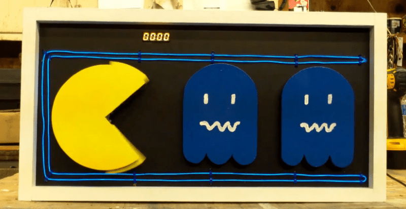
[Bob’s] Pac-Man clock is sure to appeal to the retro geek inside of us all. With a tiny display for the time, it’s clear that this project is more about the art piece than it is about keeping the time. Pac-Man periodically opens and closes his mouth at random intervals. The EL wire adds a nice glowing touch as well.
The project runs off of a Teensy 2.0. It’s a small and inexpensive microcontroller that’s compatible with Arduino. The Teensy uses an external real-time clock module to keep accurate time. It also connects to a seven segment display board via Serial. This kept the wiring simple and made the display easy to mount. The last major component is the servo. It’s just a standard servo, mounted to a customized 3D printed mounting bracket. When the servo rotates in one direction the mouth opens, and visa versa. The frame is also outlined with blue EL wire, giving that classic Pac-Man look a little something extra.
The physical clock itself is made almost entirely from wood. [Bob] is clearly a skilled wood worker as evidenced in the build video below. The Pac-Man and ghosts are all cut on a scroll saw, although [Bob] mentions that he would have 3D printed them if his printer was large enough. Many of the components are hot glued together. The electronics are also hot glued in place. This is often a convenient mounting solution because it’s relatively strong but only semi-permanent.
[Bob] mentions that he can’t have the EL wire and the servo running at the same time. If he tries this, the Teensy ends up “running haywire” after a few minutes. He’s looking for suggestions, so if you have one be sure to leave a comment.


I’m not seeing a schematic, but I don’t see any transistors, SCRs or relays in the parts list. I’d suggest a couple transistors wired up as switches to drive the EL wire and servo. Also, make sure the power supply is sufficient, as dips can cause microcontrollers to operate erratically.
Quote: “[Bob] mentions that he can’t have the EL wire and the servo running at the same time. If he tries this, the Teensy ends up “running haywire” after a few minutes. He’s looking for suggestions”
100uF to 1000uF capacitor to ground on the ‘IN’ side of the 7805 and a 10uF capacitor to ground on the ‘OUT’ side of the 7805. There is room for them on the circuit board. Then if you still have trouble it’s because the power supply (looks like plug pack / wall wart) has an underrated current for the project.
PS: The 7805 needs and absolute minimum of 7 Volts in.
The power supply is 12v 1A
5″ of el wire will be about 2 Watts. Add a Watt for the inverter, makes 3 Watt. 3 Watts from 12 Volts is 250mA and that leaves 750mA for everything else. At 750mA the 7805 would be dissipating 5.25 Watts so it would be very hot to touch and also dropping out as 750mA is too much for a 7805 without a heatsink.
If the 7805 is cool / slightly warm then add a 4700uF 25 Volt capacitor on the input of the 7805 ‘IN’ or where the wire splices are. If it is getting hot then use a 2700uF to 3300uF or 4700uF capacitor and put a heatsink in the 7805.
My suspicion is that you simply have noise. The regulator board has traces that are running parallel to the el wire on the other side of the board and that is not good. It would be better placed away from the path of the el wire.
I don’t know what a servo drains but I wouldn’t imagine it to be more than a couple of hundred mA.
In any case the first thing to do is to put a capacitor on the ‘IN’ side of the 7805 (or the splices) as this is standard practice and even more important when the 7805 is some distance from the source (plug pack / wall wart).
the pieces are cut on a band-saw, not a scroll saw.
You’re right. When I was writing that sentence I had intended to go back and reference the video to make sure I remembered correctly. Obviously I forgot. Thanks for pointing it out though because they are definitely not the same thing.
As with others, I’d suspect there’s not enough current on the power supply. It’s an easy (and likely free for any decent scavenger) thing to swap and test. A second possibility is noise coming back on the ground. I’ve experienced some issues with this when using EL wire/panels in the past.
Agree with the noise thingy. EL wire need high frequency voltage to operate, this can create some disturbances. I guess using some shielded cables with the shield connected to the ground and tying the ground to earth would help a little.
Vice versa, not visa versa XD
Awesome video going over the build.
When I saw the headline, I envisioned a Pac-Man traveling around the clock circle, eating up numbers as time passed. The Pac-Man would then actually have something to do with the timekeeping function. I’d create it myself if I had free time, but I’d like to encourage someone else to pursue the idea.
My proposed version: No LCD screens (too easy!). Seven-segment displays for the digits. I’d make each flicker and blink out as the Pac-Man passes over it, while the previous number flickers back into visibility. That takes care of the hours function.
For the minutes function, a pulsating LED power pellet (at the end of the minute hand) that the Pac-Man appears to be endlessly chasing. Power to the LED? Brushes are obvious, but perhaps it could be done by induction for low maintenance and superior geekiness.
The Pac-Man mouth opens and closes at one-second intervals.
I suppose you could modify a conventional clock mechanism if you had one powerful enough to carry all this stuff. But don’t just attach a Pac-Man image to the end of a hour hand on a ordinary clock mechanism–the character needs to rotate once each 12 hours so that its mouth always faces the next number. So, perhaps pulleys and a belt attached to the hour hand gears to generate the rotation.
Maybe the opening & closing mouth could be driven by a push rod (like a piston) attached to the second hand gears at the hub, for maximum mechanical glory (though, it might be a rather chattery, finicky mechanism). Definitely best if it’s a real mechanical mouth, but as a practical compromise *maybe* some sort of LED or LCD arrangement would be acceptable.
And, I suppose LCD digits could be used if you wanted something fancier than block digits for the numbers. But definitely a mechanical Pac-Man, to make the project truly impressive.
Can anyone suggest better alternatives to the ideas above?
I think you could do quite well selling this as a product, assuming no copyright issues.
(In case it’s not obvious, I intend that this be in the round form of a conventional clock.)
[edit] Ignore the complications with the rotating Pac-Man — I mixed up two very different ideas for how the hour function would work, and the result I posted doesn’t make sense. Obviously, if the character is on the end of a conventional hour hand, the rotation will take care of itself.
What about a custom Pac-man maze in the shape of 88:88, where Pac-man runs by every minute and eats the appropriate dots to change the numbers?
this guy gets it
wtf is this shit for? the 7-segments would have been enough
Poser to get the best deal for a while ago but the other day that is not the only one who can help us with this new pacman will help us fight the ghost.
Attention woodworkers: is the technique used at the 2:00 mark to cut out a square hole the best way he accomplish this?
The awkward looking fluffing around that he’s doing is exactly how I would cut out this hole, but all the while I would be thinking to myself: “what am I doing wrong? surely this isn’t how you are _supposed_ to do it?”
How are you supposed to do it? Or is this the correct way?
I do the same. A hole in diagonal corners and then coping saw but I finish with a rasp or file depending on the wood. On a thin sheet like this that you only see one side of when finished, I would just use a hammer and chisel, much faster.
“Clock eats time” made me think of “Muzzy in Gondoland”…