Reverse Engineer A VFD After Exploring How They Work

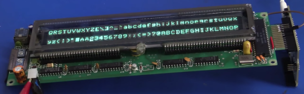
[Dave Jones] got his hands on a really wide, 2-row Vacuum Fluorescent Display. We’ve come across these units in old equipment before and you can get them from the usual sources, both new and used, but you need to know how to drive them. This recent installment of the EEVblog reverse engineers this VFD.

The function of these displays is pretty easy to understand, and [Dave] covers that early in the video after the break. There is a cathode wire and phosphorescent coated anodes. When current is applied the anodes glow. To add control of which anodes are glowing a mesh grid is placed between the anodes and the cathode wire. Applying negative potential to the grid prevents the electrons from traveling to the anode so that area will not be lit.

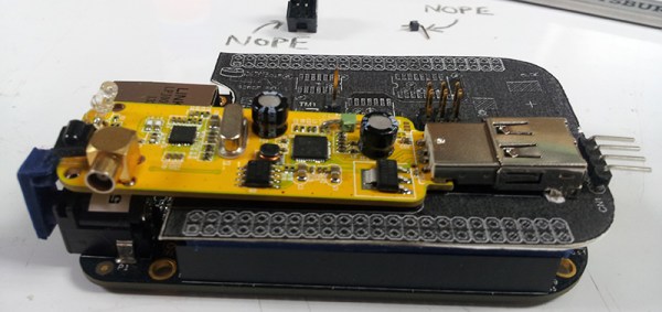
Now driving this low-level stuff is not easy, but rest assured that most VFDs you find are going to have a driver attached to them. The reverse engineering is to figure out the protocol used to control that driver. On this board there is a 2-pin connector with a big electrolytic filtering cap which is a dead giveaway for power rails. Looking at the on-board processor which connects directly he ascertains that the input will be 5V regulated since this is what that chip will expect. Connecting his bench supply yields a blinking cursor! [Dave] goes on to pump parallel data and test out the control pins all using an Arduino. He finds success, sharing many great reverse engineering tips along the way.

We often call this type of thing a dark art, but that’s really just because there aren’t a lot of people who feel totally comfortable giving it a try. We think that needs to change, so follow this example and also go look at [Ben Heckendorn’s] recent LCD reverse engineering, then grab some equipment and give it a try for yourself. We want to hear about your accomplishments!

Continue reading “Reverse Engineer A VFD After Exploring How They Work”

Laser Food

Caramelizing Sugar With A Laser

If you happen to have access to a laser cutter, you’re bound to try cutting or engraving something it wasn’t designed for. We know we have. [Bonnie] and her friend [Brenda] decided to try something new — caramelizing sugar with a laser.

Laser SugarAt their local hackerspace, NYC Resistor, they brought in some chocolate squares and colored sugar and started tinkering with the laser. It’s a 60W CO2 laser by Epilog. After testing a few different options they ended up with the following setting for optimum sugar caramelizing with only one pass:

Speed 100
Power 30
DPI 300

By spreading a thin layer of sugar over top of the chocolate, you can effectively melt and bond the sugar to the chocolate — we suspect playing with the laser focus will also help you fine tune the process for your own confections.

You could just etch the chocolate with the laser as well — but that’s not quite as cool. Perhaps try to up your sushi game, why not laser engrave seaweed before rolling? Or make the perfect laser-cut gingerbread house thanks to designing it in CAD?

Checking Populated PCB Clearance With A 3D Printer

Laying out one PCB, sending it out to a fab, stuffing it with components, and having the whole thing actually work when you’re done is a solved problem. Doing the same thing and having it plug in to another PCB… well, that’s a bit harder. Forget about building a PCB and having it fit inside an enclosure the first time.

The usual solution to this problem is printing the board to be fabbed on a piece of paper, take some calipers, and measure very, very carefully. Extra points for sticking a few components you’re worried about to the paper before lining the mechanical prototype up to the existing board. [N8VI] over at the i3 Detroit hackerspace had a better idea – print the whole thing out on a 3D printer.

[N8VI] is working on a software defined radio cape for a BeagleBone. He was a bit concerned about a few caps getting in the way of a board stack. This was tested by printing out a bit of plastic in the shape of the new board, adding header spacers and parts that might be troublesome.

While the idea is great, there’s not much in the way of a software solution or a toolchain to make plastic copies of completed boards. We know rendering 3D objects from KiCAD is rather easy, but there aren’t many tools available for those of us who are still stuck with Eagle. If you know of a way to print populated boards, drop a note in the comments.

Midwest RepRap Festival, March 20-22nd

Right now there are two emails in my inbox inviting me to 3D printer conventions. If you’re not familiar with how these cons go, here’s a quick recap: a bunch of 3D printer manufacturers set up their booths the day before, put a printer behind an acrylic enclosure, start a very complex print, and come back the next day. This printer finally completes the print sometime Sunday afternoon, a bunch of people walk by the booths, and the entire venue is filled with enough morose faces as to be comparable to one of the higher circles of hell.

The Midwest RepRap Festival is not this con. It is, to the best of my knowledge, the only 3D printing convention that isn’t a trade show. It’s a blast, it’s March 20th through the 22nd, and we’re going to be there.

This will be our second expedition to the MRRF. Last year we saw 3D printed resin molds, and a strange Core XZ printer from [Nicholas Seward], the mind that brought you the odd Reprap Wally and Simpson. The most interesting man in the universe was there with a Smoothieboard. There were talks on 3D Bioprinting by [Jordan Miller] from Rice University, and everyone ate 3D printed waffles. If you’re looking for the possibilities 3D printing offers, this is the con to go to. If you’re looking for people to sell you stuff, look elsewhere.

This event is organized by the folks at SeeMeCNC, and it will be held on their home turf of Goshen, Indiana. Yes, you will be passing Amish buggies on the way to the event. Even though the MRRF is being held in the middle of nowhere, it was absolutely shocking how many people turned up last year and how good the con was. To put this in perspective, I’m driving nine hours to MRRF, and going to Maker Faire NYC takes me four hours. If I had to choose one 3D printing event to go to, this would be the one. That’s not just because I’m told there will be a t-shirt cannon at MRRF.

The event is free and open to everybody. You can just show up, although it would be a good idea to register. You’ll see the World’s Largest 3D Printed Trash Can. Yes, I’m serious. Call Guinness.

EVA: What’s On Telly For The Visually Impaired

[chewabledrapery] has certainly used his Raspberry Pi for good. His girlfriend’s grandfather is growing more visually impaired as time goes on. He likes to watch telly, but has trouble reading the on-screen information about the channel and programming. To that end, [chewabledrapery] has built an electronic voice assistant called EVA, who fetches the telly schedule from a web service and reads it aloud in her lovely voice that comes courtesy of Google Translate’s TTS function.

Under EVA’s hood is a Raspberry Pi. A USB hub powers the Pi and holds a small USB soundcard, a Wi-Fi dongle, and a USB daughterboard that the controller plugs into. The daughterboard is from a USB keyboard, which makes another appearance in the awesome controller. It’s made of a joystick and two arcade buttons that use the USB keyboard’s controller to interact with Python scripts.

[chewabledrapery]’s scripts make formatted requests to a web service called atlas, which returns JSON objects with the TV schedule and content descriptions. EVA then turns to Google Translate, speaking the formatted text through a small amplifier and salvaged PC speaker. In order to minimize the number of web calls, some of EVA’s frequent musings are stored locally. A full tour of EVA is after the break.

We love to see hacks that help people. Remember this RFID audio book reader?

Continue reading “EVA: What’s On Telly For The Visually Impaired”

Design & Build Part 2: Multi-Band, Phasing SSB, And SDR


Amateur radio is the ultimate hacker’s hobby. You can design, build, and put on the air your own high power transceivers. And with this homemade gear you are able to reach out directly, not relying on any infrastructure whatsoever, to connect with people all over the world. It is a thrilling experience to communicate with that long distance station using equipment you created, where you know at that instant what every single transistor is doing as you key down the mic.

In a previous post I described how SSB radio equipment worked and provided an example of a single-band 20m SSB transceiver. In this post I will discuss a multi-band SSB transceiver, an entire homemade amateur station including amplifiers, and conclude with software defined radio (SDR) that you can make in one weekend.

Continue reading “Design & Build Part 2: Multi-Band, Phasing SSB, And SDR”

Arduino Zero Pro Soft Release?

There’s an updated product page for the Arduino Zero, now called the Arduino Zero Pro, up on Arduino.org, one of the two dueling “Arduinos”.

We first covered the Arduino Zero in May 2014, and shortly thereafter even got to see a development prototype in the flesh. Based an Atmel’s ARM Cortex-M0+ chip, it’s built on a faster processor than the AVR Arduini, and it includes Atmel’s Embedded Debugger which serves as a USB-to-serial channel and on-chip debugging peripheral. But so far all we’ve seen is the prototype.

Now, there’s schematics and Eagle files available that are dated January 7, 2015. The Arduino.org site says that the Zero Pro is “Available now!” but we couldn’t see any in stock yet at any of our favorite online electronics distributors. Maybe we’re looking in the wrong places (unlikely) or maybe it’s just a matter of time.

Anyway, two things struck us in our casual perusal of the new Zero Pro info.

First of all, compared to (pictures of) the prototype versions, there’s more and larger decoupling capacitors scattered all over the board, from the power supply to the Embedded Debugger chip, to a really beefy 4.7uF tantalum capacitor buffering the analog reference voltage level. This suggests there’s been some real-world testing and a shakedown of some of the prototype’s design bugs. That’s all good, and we hope it’s a sign that it’s really coming to market soon.

Secondly, given the ongoing trademark dispute, even the annotations to the schematic for the Zero Pro become interesting. On opening up either the PDF schematic (PDF, naturally) or any of the Eagle files, there’s the usual “Do not finalize a design with this information” boilerplate. But where it used to read “Arduino is a registered trademark. Use of the ARDUINO name must be compliant with http://www.arduino.cc/en/Main/Policy ” it now reads:

“Arduino” name and logo are trademarks registered by Arduino S.r.l. in Italy, in the European Union and in other countries of the world.

(After noticing this change, we went back and compared the “rev3” Uno schematics PDF on arduino.cc to the “rev3E” schematics on arduino.org. Yup, same change in the legal notice.)

We’re not lawyers, but one of the “other countries of the world” that’s conspicuously missing from the claim is the U.S. of A. where Arduino LLC presumably holds the trademark. We’re still trying to make sense of all this, but it’s funny to see the legal battle playing itself out in annotations of Eagle schematics, no?

Stay tuned for more coverage of the Arduino vs Arduino legal battle and, of course, reviews of new hardware as it comes out.

And thanks [Marc] for the tip to the new board release.